
Universal Servo Mounting System
Microservo installation and removal made easier
Robert Boyce
MOUNTING MICROSERVOS in a small sailplane can be a real problem.
The servo tabs are so small that their mounting holes end up at the very edge of the wooden rail. This results in screw holes that tend to split out, resulting in inadequate holding strength. After a few installation-and-removal cycles, structural integrity is completely lost.
Another problem is that some servo manufacturers use large rubber grommets as strain-relief on the wires where they exit the servo case. This results in a protrusion that will hang up on the rail during installation and removal.
Because of these problems, most modelers cut off the servo tabs and glue the servos to the bottom of the fuselage. Although this is a simple solution, it is not acceptable to me. Removal and reinstallation can be a real nightmare.
I recently bought a Gnat sailplane and decided to resolve this mounting problem once and for all. I will start by showing a servo rail design that satisfies the needs of the small sailplane, since they have the most-demanding design constraints. Then I will show how this design can be easily modified to accommodate larger sailplanes and servos.
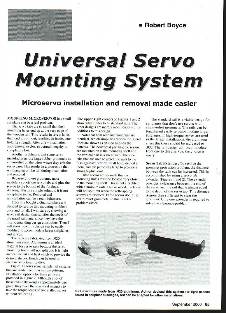
The rails are fabricated from .020 aluminum sheet. Aluminum is an ideal material for servo rails because the wooden mounting holes will not split out. It is light and can be cut and bent easily to provide the desired shapes. Bends can be used to increase structural rigidity.
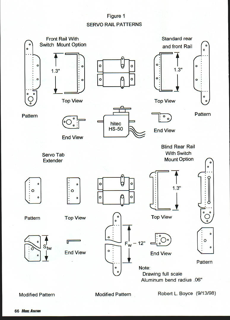
Figure 1 shows some sample rail systems that are made from four simple patterns. Installation options for these parts are provided in Figure 2. Although a set of these rails only weighs approximately one gram, they have the structural integrity to take the torque loads of two stalled servos without deflecting.
The upper right corners of Figures 1 and 2 show what I refer to as standard rails. The other designs are merely modifications of or additions to this design.
Note that both rear and front rails are identical, which simplifies fabrication. Bend lines are shown as dashed lines on the patterns. The horizontal part that the servos are mounted on is the mounting shelf and the vertical part is a shear web. The glue tabs that are used to attach the rails to the fuselage have several small holes drilled in them, and are purposely larger to provide a stronger glue joint.
Hitec servos are so small that the mounting holes must be located very close to the mounting shelf. This is not a problem with aluminum rails. Unlike wood, the holes will not split out when the self-tapping screws are inserted. These servos don't use strain-relief grommets, so this is not a problem either.
The standard rail is a viable design for sailplanes that don't use servos with strain-relief grommets. The rails can be lengthened easily to accommodate larger fuselages. If high-torque servos are used in the larger installations, the aluminum sheet thickness should be increased to .032. The rail design will accommodate from one to three servos; the choice is yours.
Servo Tab Extender
To resolve the grommet protrusion problem, the distance between the rails can be increased. This is accomplished by using a servo tab extender (Figures 1 and 2). The extender provides a clearance between the end of the servo and the rail that is almost equal to the depth of the servo tab. This distance is more than sufficient to clear the grommet. Only one extender is required to solve the clearance problem.
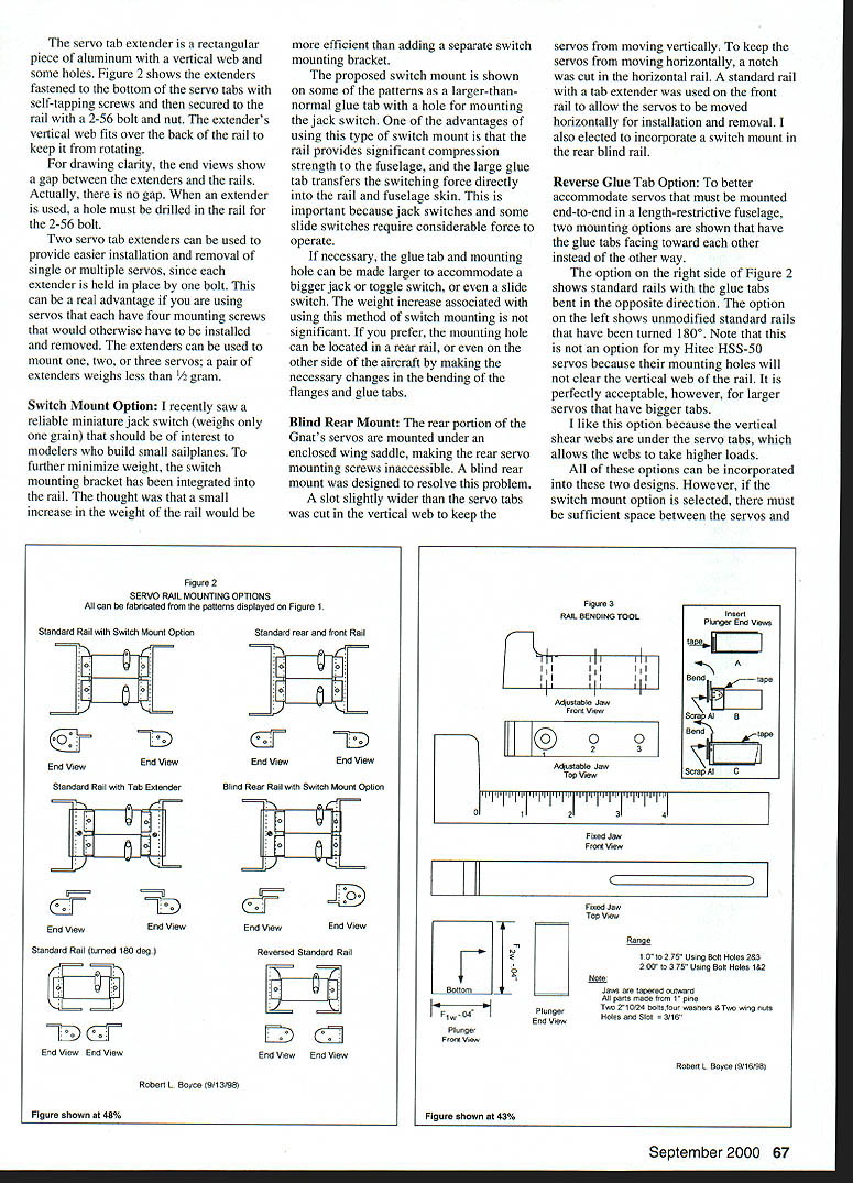
The servo tab extender is a rectangular piece of aluminum with a vertical web and some holes. Figure 2 shows the extenders fastened to the bottom of the servo tabs with self-tapping screws and then secured to the rail with a 2-56 bolt and nut. The extender's vertical web fits over the back of the rail to keep it from rotating.
For drawing clarity, the end views show a gap between the extenders and the rails. Actually, there is no gap. When an extender is used, a hole must be drilled in the rail for the 2-56 bolt.
Two servo tab extenders can be used to provide easier installation and removal of single or multiple servos, since each extender is held in place by one bolt. This can be a real advantage if you are using servos that each have four mounting screws that would otherwise have to be installed and removed. The extenders can be used to mount one, two, or three servos; a pair of extenders weighs less than 1/2 gram.
Switch Mount Option
I recently saw a reliable miniature jack switch (weighs only one grain) that should be of interest to modelers who build small sailplanes. To further minimize weight, the switch mounting bracket has been integrated into the rail. The thought was that a small increase in the weight of the rail would be more efficient than adding a separate switch mounting bracket.
The proposed switch mount is shown on some of the patterns as a larger-than-normal glue tab with a hole for mounting the jack switch. One of the advantages of using this type of switch mount is that the rail provides significant compression strength to the fuselage, and the large glue tab transfers the switching force directly into the rail and fuselage skin. This is important because jack switches and some slide switches require considerable force to operate.
If necessary, the glue tab and mounting hole can be made larger to accommodate a bigger jack or toggle switch, or even a slide switch. The weight increase associated with using this method of switch mounting is not significant. If you prefer, the mounting hole can be located in a rear rail, or even on the other side of the aircraft by making the necessary changes in the bending of the flanges and glue tabs.
Blind Rear Mount
The rear portion of the Gnat's servos are mounted under an enclosed wing saddle, making the rear servo mounting screws inaccessible. A blind rear mount was designed to resolve this problem.
A slot slightly wider than the servo tabs was cut in the vertical web to keep the servos from moving vertically. To keep the servos from moving horizontally, a notch was cut in the horizontal rail. A standard rail with a tab extender was used on the front rail to allow the servos to be moved horizontally for installation and removal. I also elected to incorporate a switch mount in the rear blind rail.
Reverse Glue Tab Option
To better accommodate servos that must be mounted end-to-end in a length-restrictive fuselage, two mounting options are shown that have the glue tabs facing toward each other instead of the other way.
- The option on the right side of Figure 2 shows standard rails with the glue tabs bent in the opposite direction.
- The option on the left shows unmodified standard rails that have been turned 180°.
Note that this is not an option for my Hitec HS-50 servos because their mounting holes will not clear the vertical web of the rail. It is perfectly acceptable, however, for larger servos that have bigger tabs.
I like this option because the vertical shear webs are under the servo tabs, which allows the webs to take higher loads.
All of these options can be incorporated into these two designs. However, if the switch mount option is selected, there must be sufficient space between the servos and the switch.
Modifying the Designs to Fit Your Servos
The servo rails and patterns shown in Figures 1 and 2 were sized to accommodate the Hitec HS-50, JR341, JR3021, and Futaba 33 class of servos, which have a servo tab depth of 3/16 (.187) inch.
If you are going to use larger servos with bigger mounting tabs, do the following:
- Trace one of your servo tabs, including the mounting holes, on a thin piece of cardboard (an old file folder works great).
- Take your new pattern and measure the depth of the servo tab. Divide by .187 inch. This number is used to determine the percentage that your servo tabs are larger than the ones shown on the drawings.
- Have Figures 1 and 2 enlarged on a copy machine by this percentage. When this is accomplished, your servos should fit the new Figures 1 and 2 patterns. Make a couple of extra copies of your new patterns.
Fit the Fuselage
- If the fuselage width is less than 1.75 inches, use .020 aluminum sheet.
- If your fuselage is between 1.75 and 2.25 inches wide, consider using the standard rail turned 180°. If this is not acceptable, go to .032 sheet.
- For all fuselages wider than 2.25 inches, use .032 aluminum sheet.
To determine the inside width of your fuselage accurately, mount your servos with wood screws to a couple of temporary wood rails (1/4 inch square pieces of balsa) that are as long as the outside width of your fuselage. Next, sand these temporary rails until they fit snugly inside the fuselage where you want to mount the servos. Finally, measure the length of the balsa rails. If they have slightly different lengths, use the average length to size the patterns. This length will be used to modify your patterns to fit your fuselage.
Cut out the rail pattern you plan to build and separate it into two pieces as shown in the example at the bottom of Figure 1.
Lay the two pieces of the pattern on a piece of paper and separate the pieces by the distance shown on the modified pattern of Figure 1. FW is simply the fuselage width determined in the paragraph above. Subtract .12 inch if you are using .020 aluminum sheet. If you are using .032 aluminum, subtract .20 inch.
Temporarily tape the pattern down at each end. Extend the three vertical lines to fill in the gap. Cut out the servo tab pattern you made previously and place it on your revised rail pattern where you would like to locate your servo. Use a straight pin to locate the servo mounting holes.
Draw the servo mounting holes on your revised pattern. To avoid confusion, use correction fluid (Wite-Out® or similar) to cover the old servo mounting holes. If you are happy with your new modified pattern, tape it down permanently.
Use the same procedure to modify any other rail patterns you plan to build. If you are going to use the servo rail extender, modify its pattern to fit your servos. Use the same procedure you used to modify the rail pattern. For this pattern, Sw is the servo tab width. If you are going to mount more than one servo on the tab extender, simply measure the combined width of the servo tabs and use that value for Sw.
Make some extra copies of all of your modified patterns, and you are ready to start construction.
Rail-Bending Tool
One difficulty I encountered in building the rails was that I could not consistently bend the glue tabs to provide the desired rail length. I also bent a few rails in the wrong direction, so they had to be scrapped.
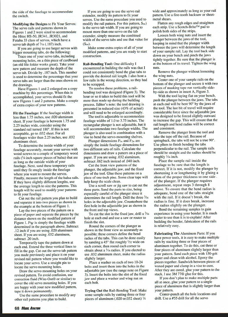
To resolve these problems, a rail-bending tool was designed (Figure 3). The hour or so it takes to build this tool will be more than made up during the building process. Editor's note: the tool drawing is presented in reduced size (43% of actual) and will need to be enlarged accordingly.
The tool is adjustable to accommodate fuselage widths of 1.0 to 3.75 inches. The rectangular plunger is not adjustable, but it will accommodate two fuselage widths. The plunger is also used in combination with a vise to bend the servo-mounting shelves.
Plunger dimensions FW and F2 are simply the inside fuselage dimensions for two different sets of rails. Calculate the dimensions and draw a pattern on a piece of paper. If you are using .032 aluminum, subtract .062 inch instead of .040 inch.
Cut the front view patterns of the fixed plunger, the adjustable jaw, and the jaw of the tool. Glue these patterns on a piece of one-inch pine. Some clear tape will help keep the scale clean.
Use a scroll saw or jig saw to cut out the three parts. Sand the parts to size, being especially careful of the plunger since it determines the rail length. Drill the three 3/16 holes in the adjustable jaw. Counterbore the first hole in the adjustable jaw as shown in the front and top views.
To cut the slot in the fixed jaw, drill a 3/16 hole at each end and use a saw or router to finish the slot.
Round the corners of the plunger as shown in the front view as accurately as possible; these corners define the bend radius of the tabs. This can be done easily by sanding a 45° flat roughly 1/32 wide on each corner, then round each corner to obtain about a 1/16 radius. If you elected to use .032 aluminum sheet, make the radius slightly larger.
Place a washer on each of two 10-24 bolts and insert them into the holes in the adjustable jaw (see the range note on Figure 3). Insert the bolts into the slot of the fixed jaw and place a washer and wing nut on each bolt.
Trying Out the Rail-Bending Tool
- Make some sample rails by cutting three or four pieces of aluminum (.020 or .032 sheet) 1/4 inch wide and approximately as long as your rail pattern. Use a fine-tooth hacksaw or sheet-metal shears.
- Flatten any rough edges and straighten each strip. Use a Scotch-Brite™ pad to polish both sides of the strips.
- Loosen both wing nuts and insert the plunger between the jaws of the tool, keeping in mind that the plunger width between the jaws will determine the length of your sample rail. Lay the tool back side down on your bench and pinch the jaws tightly together. Be sure that the plunger is at the bottom of its travel. Tighten the wing nuts.
- Remove the plunger without loosening the wing nuts.
- Center one of your sample rails on the bottom of the plunger and secure it with two pieces of masking tape run vertically side-by-side as shown in insert A, Figure 3.
- With the tool laying flat on your bench, push the plunger between the jaws. The tabs at each end will be bent 90° by the jaws of the tool. The last bit of travel will require considerable force since the adjustable jaw was designed to be forced slightly outward to increase the gap. This will ensure that the rail length and bend radius will be correct and consistent.
- Remove the plunger from the tool and take the tape off the rail. Because of springback, the tabs will not be a true 90°. Use pliers to finish bending the tabs perpendicular to the rail. The sample rails should be straight and the radius should be roughly 1/16 inch.
- Place the sample rail inside the fuselage to be sure that the length is correct. If it is not, modify the plunger by shortening it or lengthening it by gluing a shim of the proper thickness to one side of the plunger. If the plunger requires adjustment, repeat steps 3 through 8 above. To ensure that the bend radius is adequate, bend one of the tabs straight with the rail. If it doesn't break, the radius is fine. If it does break, increase the radius slightly on the plunger.
Bend the remaining samples to gain experience in using your bender. It is much easier to use than it is to explain! After building the bender, fabrication of the rails is relatively easy.
Fabricating The Aluminum Parts
If you have power tools, it is easy to make multiple rails by stacking three or four pieces of aluminum together. To do this, cut three or four pieces of aluminum slightly larger than your pattern. Sand each piece with 150-grit sandpaper and clean with alcohol. Epoxy the pieces together. Sand between pieces and use small clamps to hold them in a vise to cure. After they are cured, cut the pattern from the stacked material using a hacksaw or tin snips.
If you don't plan to make multiple parts from a single pattern, use a single piece of aluminum that is slightly larger than your pattern.
Center-punch all the hole locations and drill. Use a #55 drill for all the servo mounting holes and approximately a 5/32 drill for the mounting screws. Deburr, polish, and bend the tabs as described above.
Bending the Glue Tabs
For the rail options shown in Figure 2, always bend the glue tabs first and then the mounting shelf. The one exception is if you are building the reversed standard rail. For this option you must first bend the servo-mounting shelf and then the glue tabs.
- Place the aluminum part that still has the paper pattern attached on the bottom of the plunger (insert A, Figure 3) as was done with the sample rails. Be sure the part is centered on the plunger and oriented so that the paper pattern is positioned away from the plunger. Temporarily attach it in place with masking tape.
- To ensure that the tabs and servo mounting shelves are bent in the correct direction, always perform the following procedure:
- Locate the option on Figure 2 that corresponds to your part and select the rail you are going to make (the front or rear rail).
- Lay the plunger flat on Figure 2 with the front of the plunger up and with the plunger bottom centered between the glue tabs of the rail you are building. The aluminum part will be vertical and directly over the vertical web of the drawing.
- For all options except the blind rear rail, the servo-mounting shelf should be up. For this option, the shelf should be down. If necessary, simply turn the plunger over.
- Look at the glue tabs of your part and be sure they are located on the correct end of the rail. If they are reversed, remove the tape and flip the part over horizontally and retape. If you had to flip the part, repeat steps A through D.
- Tape the part to the plunger as you did before with the sample part (insert A, Figure 3). Do not overlap the tape. Now you are ready to bend the glue tabs.
- Use the rail-bending tool and follow the same procedure you previously went through on the sample rails to bend the glue tabs. Make sure the tabs are perpendicular and straight.
- Bend the tabs on any other rails you are making now.
Bending the Servo Mounting Shelf
- Tape the aluminum part to the bottom of the plunger with the glue tabs on each side of the plunger and the servo-mounting shelf sticking above the front of the plunger. The horizontal dashed bend line should be in line with the front edge of the plunger. Tape the part to the plunger tightly (insert B, Figure 3).
- Cut a piece of scrap .020 or .032 aluminum about 3/4 inch wide and 1-1/2 inch longer than the length of the dashed bend line of your part. Roughly center the scrap piece over the bend line (insert B, Figure 3) and clamp it in place while clamping the unit in a vise. Be sure that the very front of the plunger is in line with the top of the vise jaws. The scrap of aluminum is used to provide a radius for the bend.
- Place a small piece of wood against the back side of the servo-mounting shelf. To bend the shelf, use a hammer to lay the wood lightly on the rail. Use the hammer to bend the shelf down until it is flush with the front of the plunger. Remove the plunger from the vise and deburr the bent area with a fine file or deburring tool. If necessary, finish the edge with Scotch-Brite.
- Make the other rails in the same manner.
Bending the Servo Tab Extender
With the paper pattern glued to the aluminum part, tape the part to the plunger with the shear web up and the pattern facing the plunger. Align the horizontal dashed bend line so that it is even with the top surface of the plunger.
Place a piece of aluminum scrap in front of the part and clamp it in a vise, just as you did with the servo-mounting shelf. Bend the servo tab extender shear web exactly as you did the servo mounting shelf.
Position the servo tab extender on the rail and use it as a guide to drill the #44 hole in the servo mounting shelf.
Bending the Reverse Standard Rail Option
Bend the servo-mounting rail and then the glue tabs. Start by taping the part to the bottom of the plunger (Insert C, Figure 3).
Orient the part so that the paper pattern faces outward. Position the part so that it is centered with the horizontal dashed bend line even with the top surface of the plunger and the servo mounting shelf upward.
To ensure that this option is bent correctly, perform the following procedure:
- Lay the plunger flat over the corresponding figure on Figure 2 so that the front of the plunger is up and the aluminum part is vertical and directly over the web of the drawing. Orient the plunger so that the servo mounting shelf is up and the back of the plunger faces the servo.
- Look at the glue tabs of the part and be sure they are located at the correct end of the rail. If they are reversed, flip the part horizontally and retape.
- Bend the shelf the same as the procedure outlined for bending the servo mounting shelf.
- To bend the glue tabs, tape your part so that the mounting shelf you just bent is on the front of the plunger and the vertical shear web is flat against the bottom of the plunger. The corner of the plunger should be slightly rounded so that the part will lay flat against the plunger. Tape the part to the plunger and bend the glue tabs the way you did for the sample rails.
Finishing Touches and Conclusions
Remove the paper patterns from all rails and servo tab extenders. Polish the parts with a Scotch-Brite™ pad. To ensure a good glue bond to the fuselage, sand the outside of the glue tabs with 150-grit paper, clean with alcohol, place a small amount of epoxy on a Scotch-Brite™ pad, and rub a thin coat of epoxy on the outside of each glue tab.
After the epoxy has cured, you can color the parts with a permanent marker to match your model's fuselage. Do not get ink on the outside of the glue tabs. Mount the servos to the rails and epoxy the glue tabs to the fuselage.
I hope you have enjoyed building your rails as much as I have. I know that you will be proud of the final results. The next set of rails you build will be a breeze.
Robert L. Boyce 5741 S. Crestbrook Dr. Morrison CO 80465
Transcribed from original scans by AI. Minor OCR errors may remain.

