
Universal Slow Charger
- Bob Kopski
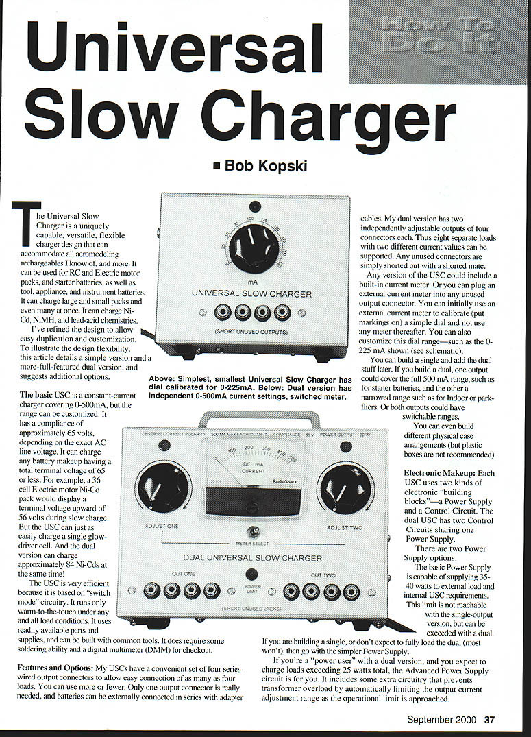
The Universal Slow Charger (USC) is a versatile charger design that can accommodate most aeromodeling rechargeable batteries and many others. It can be used for RC and electric motor packs, starter batteries, and tool, appliance, and instrument batteries. It can charge large and small packs and even many at once. It supports Ni-Cd, NiMH, and lead-acid chemistries.
I refined the design to allow easy duplication and customization. To illustrate the design flexibility, this article details a simple version and a more full-featured dual version, and suggests additional options.
The basic USC is a constant-current charger covering 0–500 mA, but the range can be customized. It has a compliance of approximately 65 volts, depending on the AC line voltage. It can charge any battery whose total terminal voltage is 65 volts or less. For example, a 36-cell electric-motor Ni-Cd pack would display a terminal voltage upward of 55 volts during slow charge. But the USC can just as easily charge a single glow-driver cell. The dual version can charge approximately 84 Ni-Cd cells at the same time.
The USC is very efficient because it is based on switch-mode circuitry. It runs only warm to the touch under all load conditions. It uses readily available parts and supplies and can be built with common tools. It does require some soldering ability and a digital multimeter (DMM) for checkout.
Features and Options
- My USCs have a convenient set of four series-wired output connectors to allow easy connection of as many as four loads. You can use more or fewer. Only one output connector is really needed; batteries can be externally connected in series with adapter cables.
- The dual version has two independently adjustable outputs of four connectors each, supporting eight separate loads with two different current values.
- Any unused connectors are simply shorted out with a shorted mate.
- Any version of the USC could include a built-in current meter, or you can plug an external current meter into any unused output connector.
- You can initially use an external current meter to calibrate (mark) a simple dial and not use any meter thereafter. You can also customize the dial range—such as a 0–225 mA range shown in the schematic.
- You can build a single unit and add the dual features later. If you build a dual, one output could cover the full 500 mA range (for starter batteries) and the other a narrow range for indoor or park flyers. Both outputs could also have switchable ranges.
- Different physical case arrangements are possible (plastic boxes are not recommended).
Electronic Makeup
Each USC uses two kinds of electronic building blocks—a Power Supply and a Control Circuit. The dual USC has two Control Circuits sharing one Power Supply.
There are two Power Supply options:
- Basic Power Supply
- Capable of supplying about 35–40 watts to external load and internal USC requirements.
- This limit is not reached with the single-output version, but can be exceeded with a dual.
- If you are building a single, or don't expect to fully load the dual, use the simpler Power Supply.
- Advanced Power Supply
- For "power users" with a dual version who expect to charge loads exceeding about 25 watts total.
- Includes extra circuitry that prevents transformer overload by automatically limiting the output current adjustment range as the operational limit is approached.
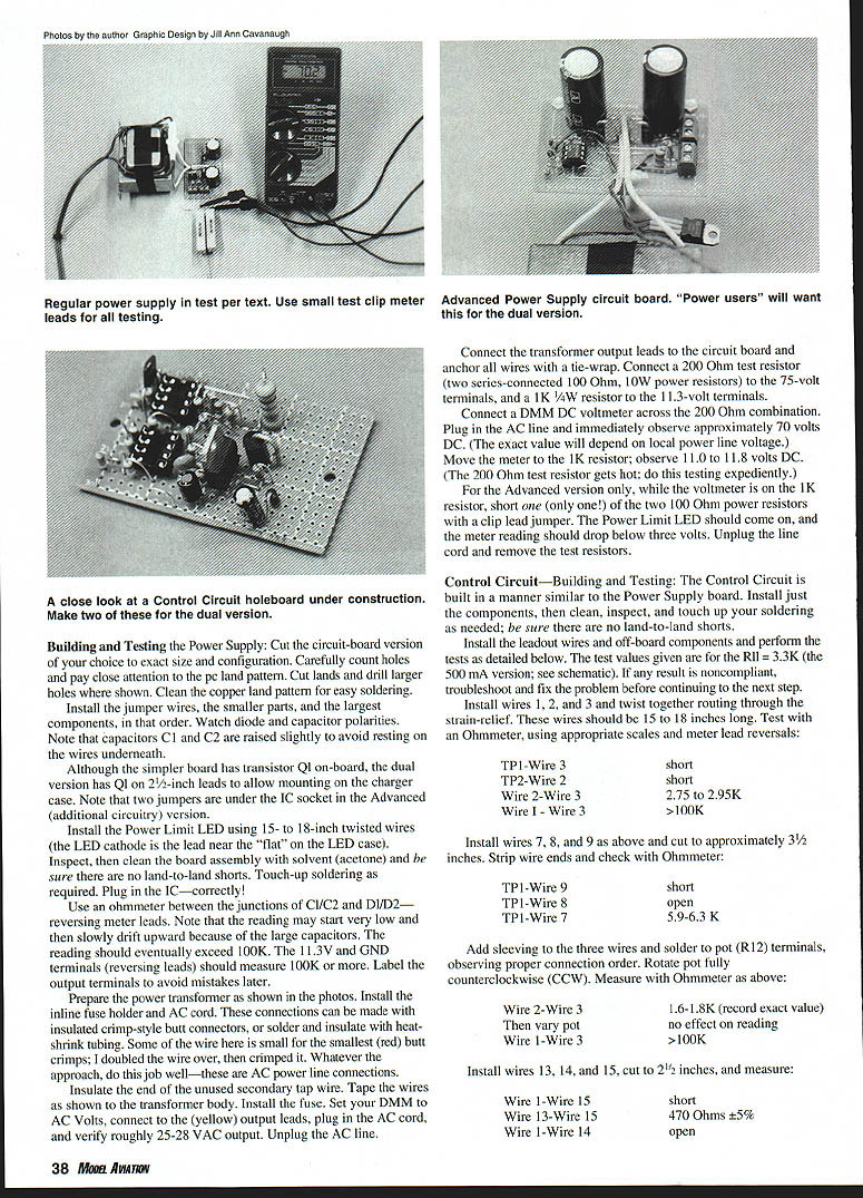
Connect the transformer output leads to the circuit board and anchor all wires with a tie-wrap. Connect a 200 Ω test resistor (two series-connected 100 Ω, 10 W power resistors) to the 75 V terminals, and a 1 KΩ 1/4 W resistor to the 11.3 V terminals.
Connect a DMM DC voltmeter across the 200 Ω combination. Plug in the AC line and immediately observe approximately 70 V DC (exact value depends on local power line voltage). Move the meter to the 1 KΩ resistor; observe 11.0 to 11.8 V DC. (The 200 Ω test resistor gets hot: perform this testing expediently.)
For the Advanced version only: while the voltmeter is on the 1 KΩ resistor, short one (only one!) of the two 100 Ω power resistors with a clip-lead jumper. The Power Limit LED should come on, and the meter reading should drop below 3 V. Unplug the line cord and remove the test resistors.
Control Circuit — Building and Testing
The Control Circuit is built in a manner similar to the Power Supply board. Install components, then clean and inspect your soldering; be sure there are no land-to-land shorts.
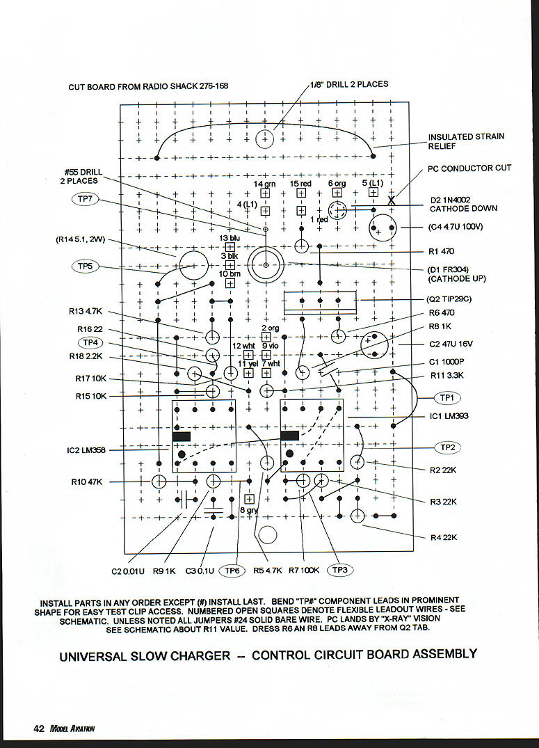
Install the leadout wires and off-board components and perform the tests detailed below. The test values given are for R11 = 3.3 KΩ (the 500 mA version; see schematic). If any result is out of specification, troubleshoot and fix the problem before continuing.
- Install wires 1, 2, and 3 and twist together routing through the strain-relief. These wires should be 15 to 18 inches long. Test with an ohmmeter, using appropriate scales and reversing meter leads if needed:
- TP1—Wire 3: short
- TP2—Wire 2: short
- Wire 2—Wire 3: 2.75–2.95 KΩ
- Wire 1—Wire 3: >100 KΩ
- Install wires 7, 8, and 9 as above and cut to approximately 3-1/2 inches. Strip wire ends and check with an ohmmeter:
- TP1—Wire 9: short
- TP1—Wire 8: open
- TP1—Wire 7: 5.9–6.3 KΩ
- Add sleeving to the three wires and solder to pot (R12) terminals, observing proper connection order. Rotate pot fully counterclockwise (CCW). Measure with an ohmmeter:
- Wire 2—Wire 3: 1.6–1.8 KΩ (record exact value)
- Then vary pot: No effect on reading
- Wire 1—Wire 3: >100 KΩ
- Install wires 13, 14, and 15, cut to 2-1/2 inches, and measure:
- Wire 1—Wire 15: short
- Wire 13—Wire 15: 470 Ω ±5%
- Wire 1—Wire 14: open
- Install diodes:
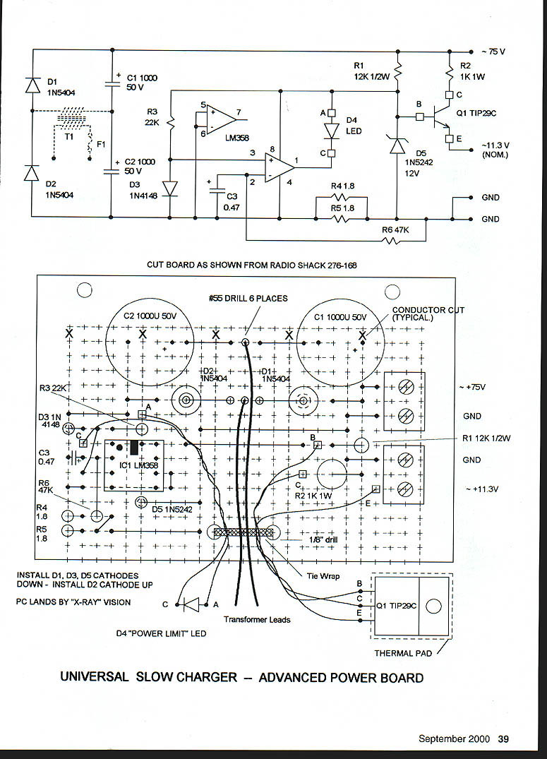
- Install D1, D3, D5 with cathodes down.
- Install D2 with cathode up.
PC lands are referenced by "X-RAY" vision (as on the artwork). D4 is the "POWER LIMIT" LED.
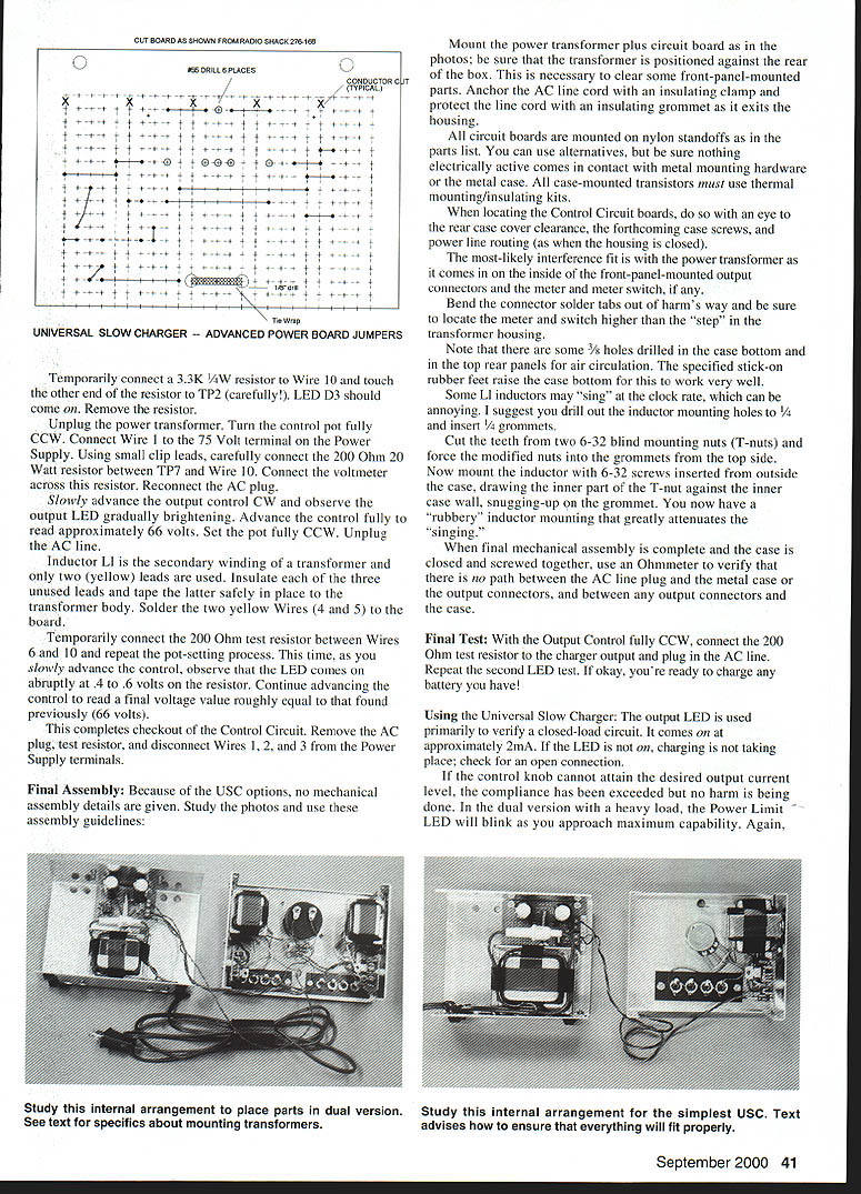
Drill and cut board per the diagram: use a #55 drill for 6 places, conductor cuts typical, 1/8" drill, and tie-wrap locations. Use the indicated thermal pad and transformer lead routing.
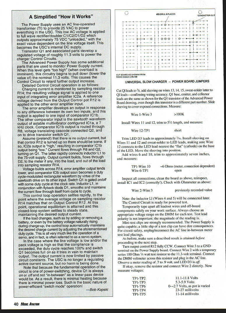
Cut Q1 leads to 3/8", add sleeving on wires 13, 14, 15, and sweat-solder to Q1 leads—confirm wiring accuracy. Q1 base, emitter, and collector leads match the Q1 transistor in the Advanced Power Board drawing, even if the part number differs. Slide sleeving to cover exposed connections. Measure:
- Wire 1—Wire 3: >100 KΩ
- Install Wires 11 and 12, trim to 5/8" length, and measure:
- Wire 12—TP: short
Trim LED D3 leads to approximately 3/16". Install sleeving on Wires 11 and 12 and sweat-solder to LED leads, making sure Wire 12 connects to the LED lead nearest the flat (cathode) on the base of the LED. Move the sleeving into position.
- Add wires 6 and 10, trim to approximately seven inches, and measure:
- TP1—Wire 10: ~6 Ω (meter and connection dependent)
- Wire 6—TP1: open
Inspect all connections, clean the board, reinspect, and install IC1 and IC2 (observe correct orientation). Check with an ohmmeter:
- Wire 2—Wire 3: previously recorded value
Note: Inductor L1 (Wires 4 and 5) will be connected later. The Control Circuit is now ready for powered test.
Temporarily tape apart all leadout wires and off-board components safely on your work surface. Always choose an appropriate voltage range on the DMM for each test. Test lead polarity is not important; the magnitude of the readings is. Mini-test clips are strongly recommended. The Power Supply is quite capable; a slip of a test clip can have dire consequences. For circuit safety, unplug/reconnect the AC line between meter test placements.
As before, make sure a described result is attained before proceeding.
- Turn output control R12 fully CCW. Connect Wire 3 to a GND terminal on the Power Supply board. Connect Wire 2 with a temporary series 100 Ω 1/4 W test resistor to the 11.3 V terminal. Connect the DMM voltmeter across this resistor and plug in the AC line. Observe a meter reading of 0.7–0.9 V, and LED D3 should be off.
If okay, remove the resistor and connect Wire 2 directly. Measure voltages:
- TP1—TP2: 11.1–11.8 V
- TP1—TP3: 5.3–5.9 V
- TP1—TP6: 0–2.7 V, as pot is varied
- TP1—TP4: 23–27 mV
- TP1—TP5: 11–14 mV
Temporarily connect a 3.3 KΩ 1/4 W resistor to Wire 10 and touch the other end of the resistor to TP2 (carefully). LED D3 should come on. Remove the resistor.
- Unplug the power transformer. Turn the control pot fully CCW. Connect Wire 1 to the 75 V terminal on the Power Supply. Using small clip leads, carefully connect the 200 Ω 20 W resistor between TP7 and Wire 10. Connect the voltmeter across this resistor. Reconnect the AC plug.
Slowly advance the output control CW and observe the output LED gradually brightening. Advance the control fully to read approximately 66 V. Set the pot fully CCW. Unplug the AC line.
Inductor L1 is the secondary winding of a transformer; only two (yellow) leads are used. Insulate each of the three unused leads and tape them safely in place on the transformer body. Solder the two yellow wires (4 and 5) to the board.
Temporarily connect the 200 Ω test resistor between Wires 6 and 10 and repeat the pot-setting process. This time, as you slowly advance the control, observe that the LED comes on abruptly at 0.4–0.6 V on the resistor. Continue advancing the control to read a final voltage value roughly equal to that found previously (~66 V).
This completes checkout of the Control Circuit. Remove the AC plug, test resistor, and disconnect Wires 1, 2, and 3 from the Power Supply terminals.
How It Works — Simplified
The Power Supply uses an AC line-operated transformer (T1) to provide about 25 VAC to power everything in the USC. This low AC voltage is applied to a full-wave rectifier/doubler (C1/C2/D1/D2) which outputs approximately 75 V DC unloaded (exact value depends on line voltage). This becomes the USC's internal DC supply.
Transistor Q1 and associated parts develop a regulated voltage of roughly 11.3 V to power the Charger Control Circuits.
The Advanced Power Supply has additional parts to monitor Power Supply current. When the level gets too high (when overload is imminent), this circuitry begins to pull down the nominal 11.3 V. This causes the Control Circuit to limit further output increase.
Detailed Control Circuit operation:
- Charging current is monitored by sampling resistor R14; the resulting voltage signal is applied to one input of integrating error amplifier IC2a. A reference voltage derived from the Output Control pot R12 is applied to the other input.
- The error amplifier develops an output in response to any difference between its inputs, and this output is applied to one input of comparator IC1b. The other comparator input is the sawtooth waveform output of an astable multivibrator configured in IC1a, a ~7 kHz clock.
- Comparator IC1b output is routed through R8, voltage-translating cascode-connected Q2, and on to drive transistor switch Q1.
- If no output current is present but control R12 is turned up, IC2a output is high, resulting in comparator IC1b output being low. Current flows through R8 and Q2, turning on Q1 and connecting inductor L1 to the 75 V supply. Output current builds, flows through D2, into the load, and out through sampling resistor R14.
- Voltage across R14 causes the error amplifier output to lower, and comparator IC1b output becomes duty-cycle-modulated by the sawtooth drive. Switch Q1 is gated on/off at the clock rate. Inductor L1, with flyback diode D1, smooths and maintains current through cycles.
- The loop settles so the average voltage on R14 matches that on R12. The closed-loop system maintains the desired output current.
- If the load changes (adding/removing a battery or the battery voltage rising during charge), the control loop adjusts duty cycle to maintain the set current.
- If line voltage is low or pack voltage is high and compliance is exceeded, duty cycle reaches 100% and Q1 is fully on; the charger then behaves like a passive-limited source. No harm is done.
- Because Q1 operates as a switch (on or off), there is minimal heating compared to a linear pass device—hence the efficiency of switch-mode operation.
— Bob Kopski
Final Assembly
Because of USC options, no detailed mechanical assembly is given—study photos and use these guidelines:
- Mount the power transformer and circuit board as shown in the photos; position the transformer against the rear of the box to clear front-panel-mounted parts.
- Anchor the AC line cord with an insulating clamp and protect the line cord with an insulating grommet where it exits the housing.
- Mount circuit boards on nylon standoffs. Ensure nothing electrically active contacts metal mounting hardware or the metal case. All case-mounted transistors must use thermal mounting/insulating kits.
- When locating Control Circuit boards, consider rear case cover clearance, case screws, and power line routing.
- Watch for interference fits between the transformer and front-panel-mounted output connectors, meter, or meter switch. Bend connector solder tabs out of harm's way and locate the meter and switch higher than the transformer housing step.
- There are 3/16" holes in the case bottom and top rear panels for air circulation; use the specified stick-on rubber feet to raise the case bottom.
- Some L1 inductors may "sing" at the clock rate. To attenuate this, drill the inductor mounting holes to 1/4" and insert 1/4" grommets. Cut the teeth from two 6-32 blind mounting nuts (T-nuts) and force the modified nuts into the grommets from the top side. Mount inductors with 6-32 screws inserted from outside the case, drawing the inner part of the T-nut against the inner case wall, snugging up on the grommet. This yields a rubbery inductor mounting that greatly reduces singing.
- When final mechanical assembly is complete and the case is closed, use an ohmmeter to verify there is no path between the AC line plug and the metal case or output connectors, and between any output connectors and the case.
Final Test
- With the Output Control fully CCW, connect the 200 Ω test resistor to the charger output and plug in the AC line. Repeat the LED test. If okay, the USC is ready to charge batteries.
Using the Universal Slow Charger
- The output LED primarily verifies a closed-load circuit. It lights at approximately 2 mA. If the LED is off, charging is not taking place—check for an open connection.
- If the control knob cannot attain the desired output current level, the compliance has been exceeded; no harm is being done.
- In the dual version with a heavy load, the Power Limit LED will blink as you approach maximum capability.
Study the internal arrangements to place parts in the dual version. See text for specifics about mounting transformers. Study the internal arrangement for the simplest USC and ensure everything fits properly.
INSTALL PARTS IN ANY ORDER EXCEPT (#) INSTALL LAST. BEND "TP#" COMPONENT LEADS IN A PROMINENT SHAPE FOR EASY TEST-CLIP ACCESS. NUMBERED OPEN SQUARES DENOTE FLEXIBLE LEADOUT WIRES—SEE SCHEMATIC. UNLESS NOTED, ALL JUMPERS ARE #24 SOLID BARE WIRE. PC LANDS ARE SHOWN BY "X-RAY" VISION. SEE SCHEMATIC ABOUT R11 VALUE. DRESS R6 AND R8 LEADS AWAY FROM Q2 TAB.
Universal Slow Charger — Control Circuit Board Assembly
Transcribed from original scans by AI. Minor OCR errors may remain.

