

Variable Voltage
by Bob Kopski
The Variable Voltage Control (VVC) is a valuable shop accessory that converts a fixed 12-volt supply to an adjustable one. It is useful to modelers who do hot-wire foam-cutting, E-modelers with motor break-in needs, and for almost any other DC low-voltage, high-current application.
The VVC is a simple, low-cost project. It has relatively few parts, and all are readily available at RadioShack® and hobby and hardware stores. It can be built with common hand tools, but does require some soldering ability. A digital multimeter (DMM), some test leads, and one test resistor are needed for checkout.
The VVC can be powered from optional 12-volt sources, including automotive, lawn-tractor, or motorcycle batteries. Line-operated 12-volt supplies, such as those used by many electric- and car-modelers, are another choice. Even a common household auto-battery charger can be used to power the VVC.
Any such supply from 10 to 18 volts will work well. The only requirement is that the source be capable of supplying the load current needed. The VVC output voltage is then smoothly variable from zero to somewhat under the input voltage level at currents upward of seven amps.
Design secret
Any simple linear circuit of this nature can get destructively hot in use. However, this VVC’s operation is made possible by water cooling an unusual, high-power Darlington transistor. The chosen part is capable of dissipating 300 watts at 25°C case temperature and 160 watts at 100°C case temperature.
Therein lies the secret to the operational success of this design. Oil is immersed in water. In normal use, it will bring the water to a slow boil at 100°C. Under these conditions, the transistor can get no hotter and the VVC operates with room to spare for power dissipation.
There is no other simple, inexpensive way I know of to accomplish the same feat.
Makeup and assembly
The overall VVC is comprised of simple subassemblies: the housing subassembly, two component subassemblies, and interwiring to tie it all together.
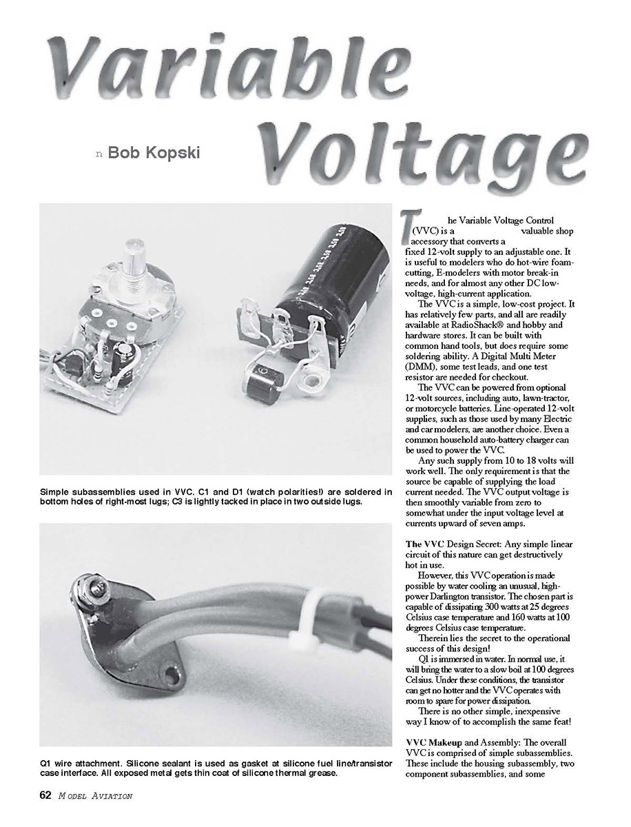
The terminal strip is cut from a standard part, and it supports three components and (later) some other wiring. Two components shown, C1 and D1, are optional.
- C1 can be in place with any source but is really only needed when the VVC uses an auto-battery charger as a power source. Its purpose is to filter the rectified ripple characteristic of such chargers.
- D1 is a protection diode. It is only needed if you feel it necessary to protect against accidental wrong-polarity connection of the input. If you use polarized connectors (or have lots of self confidence!), you do not need D1. With it, fuse F1 will blow if you hook up the input in reverse.
Whether you include C1 and D1, the terminal strip with capacitor C3 is a necessary subassembly.
The pc-holeboard subassembly is detailed in the Board Assembly drawing. This small board is cut from a larger, commonly available holeboard, and it holds seven parts. Study the pattern shown, count holes, and make sure the board is cut correctly.
Accurately assemble the components on the pc board, taking care to avoid any solder shorts. Confirm C2 polarity. Voltage adjustment control R6 is wired to the board with three short wires, but physically attached with 1/16 × 1/2-inch double-stick foam tape (auto-moulding tape is preferred). Four board leadout wires connect it to other circuit points in the housing assembly.
When all the board soldering is done, clean the board by brushing it with a solvent (e.g., flux remover, acetone), allowing it to drip away from the bottom side of the board while minimizing getting solvent on the component side. Use a lens and inspect your work.
Clear any shorts, touch up any soldering as needed, reclean, and reinspect. Please do all this as described—I know from previous articles that some people don't, then have to pay the price later. Set the board aside.
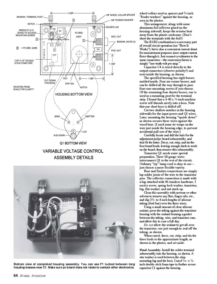
The housing subassembly is detailed in the photos and drawings. For a compact version, the author cut off the box mounting lugs and chose an ordinary coffee cup as the cooling tank for Q1. In use, water in it boils off at the rate of up to several ounces per hour depending on the task, and it is absolutely necessary to keep Q1 fully immersed.
If overall size is unimportant, you can choose a much larger water tank, such as various kinds of cookware. This way, you won't have to add water every couple of hours. Mounting everything on a wood baseplate works well.
The author uses approximately five feet of standard 18-gauge lamp cord with banana plugs as an input cable. Output connectors are two pairs of banana jacks cyanoacrylate-glued in the housing lid and wired in parallel. These allow connection of two loads (such as two similar motors in break-in) or the chosen load and a voltmeter.
R1 and R2 are 0.2-ohm five-watt power resistors connected in parallel to make a 0.1-ohm 10-watt resistor. (A standard 10-watt part is too large.) These resistors carry the output current and, depending on its value, can get hot. For this reason, they are mounted on the outside of the plastic housing in the specified combination banana/binding posts.
These banana/terminal posts are stood off from the enclosure sidewall with 1/8-inch spacers. A length of short aluminum tubing is used to make the mounting posts for the resistors.
The power-transistor mounting is the most critical mechanical detail. The transistor must be mounted so the case is fully immersed in the water of the cooling tank. A plywood washer is a handy and necessary spacer, keeping the transistor case below the rim of the cup but above the base so the case never touches the bottom. Use silicone or epoxy around the transistor base where it passes through the housing to prevent leakage.
For safety, provide some form of splash shield or filter over the cup to reduce the loss of water due to splattering and to prevent accidental contact with the hot transistor case.
Before final assembly, test the unit on a bench power supply at low input voltage and low current, confirming that the control varies smoothly and that the transistor remains stable. Check all connections, polarity, and that the cooling arrangement maintains the transistor case temperature.
The author has used this VVC to test motors up to ten amps with satisfactory results. The overall construction is inexpensive and readily repaired if needed.
Parts source notes
The high-power Darlington transistor used is commonly available from major electronic suppliers. The remaining parts are off-the-shelf items from hobby and electronics stores. Use the component values listed in the schematic and substitute only with parts of equal or greater ratings.
Wheel collars can be used as spacers and 3/4-inch fender washers against the housing, as seen in the photos. This arrangement, along with some aluminum-foil reflector glued on the housing sidewall, keeps the resistor heat away from the plastic enclosure (do not short the terminals with the foil).
The R1/R2 combination is a necessary part of overall circuit operation and is also a convenient current shunt for measurement purposes since output current flows through it. Just connect a voltmeter to the same connectors—the conversion factor is one-tenth volt per amp.
Capacitor C4 is wired directly to the output connectors (observe polarity) and rests inside the housing.
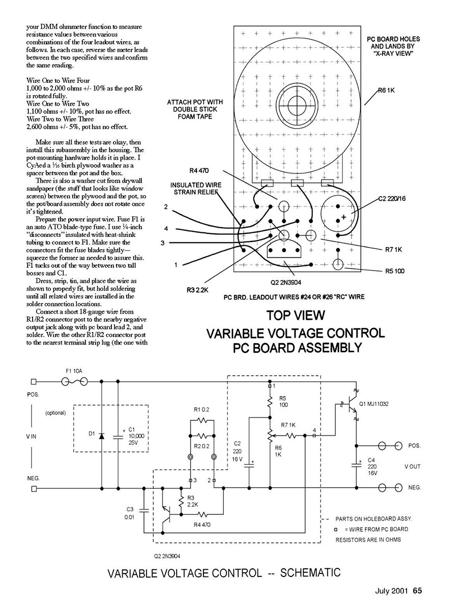
The specified housing has eight bosses molded inside. Four are corner bosses and can be drilled all the way through to pass four case-mounting screws if you choose. Of the remaining four shorter bosses, one is used as a mounting post for the terminal strip. A 4-40 × 1/4-inch machine screw self-threads nicely into a boss. Note that one short boss is drilled off.
Cut two shallow notches in the housing sidewalls for the input power and Q1 wires. Later, mounting the housing upside down secures these wires against the wood base. Use tie wraps on the wire just inside the housing edge to prevent accidental pull-out.
Carefully locate and drill the hole for the adjustment pot/pc board subassembly, and trial-fit the latter. Dress, cut, strip, and tin the four board leads, leaving enough slack to work on the board, then remove this subassembly.
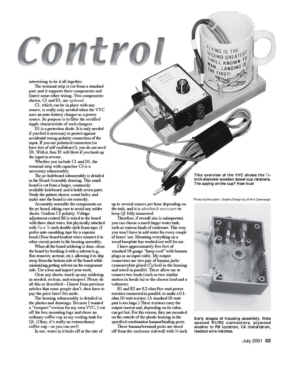
Transistor Q1 needs special preparation. Three 18-gauge wires interconnect Q1 to the rest of the circuit. Ordinary zip lamp cord is acceptable—choose a flexible variety.
- Base and emitter connections are lap solder joints of the wire to the transistor pins.
- The collector connection is made with a lug attached with #6 stainless hardware (screw, spring-lock washer, transistor lug, flat washer, and nut stack-up).
Clean this assembly with acetone or other solvent to remove flux and oils, and slip 3½ to 4-inch lengths of silicone tubing (fuel line) over the three wires. Using a small amount of clear silicone sealant, press the tubing against the transistor housing with the sealant forming a gasket between the tubing, wire, and transistor case, and allow this to cure for a full day.
Do not allow the sealant to get all over the transistor; use just enough to seal off the tubing. When cured, dress, cut, strip, and tin the three leads to the approximate length and set aside.
Final assembly
Install the solder terminal subassembly into the housing. A star washer is used between the strip mounting lug and the boss. 1/16 × 1/2-inch double-stick foam tape can be used to secure capacitor C1 against the housing.
Use your DMM ohmmeter function to measure resistance values between various combinations of the four leadout wires, as follows. In each case, reverse the meter leads between the two specified wires and confirm the same reading.
- Wire One to Wire Four: 1,000 to 2,000 ohms ±10% as the pot R6 is rotated fully.
- Wire One to Wire Two: 1,100 ohms ±10%, pot has no effect.
- Wire Two to Wire Three: 2,600 ohms ±5%, pot has no effect.
Make sure all these tests are okay, then install this subassembly in the housing. The pot-mounting hardware holds it in place. Cut a 1/8 birch plywood washer as a spacer between the pot and the box. Place a washer cut from drywall sandpaper between the plywood and the pot so the pot/board assembly does not rotate once tightened.
Prepare the power input wire. Fuse F1 is an auto ATO blade-type fuse. Use 1/4-inch disconnects insulated with heat-shrink tubing to connect to F1. Make sure the connectors fit the fuse blades tightly—squeeze the former as needed to assure this. F1 tucks out of the way between two tall bosses and C1.
Dress, strip, tin, and place the wire as shown to properly fit, but hold soldering until all related wires are installed in the solder connection locations.
Connect a short 18-gauge wire from the R1/R2 connector post to the nearby negative output jack along with pc board lead 2, and solder. Wire the other R1/R2 connector post to the nearest terminal strip lug.
Testing and use
In general, a common 10-amp auto battery charger will provide essentially all the capability you would likely ever need with the VVC. One way to use such a charger is to cut off its standard battery-clip connector, leave several inches of wire with them, install matching connectors on the charger lead-out wires, the wires of the cutoff clip, and the input wires to the VVC. Now you can use the charger with the original clip, as intended, or with the VVC. Be sure to observe connector polarity under all conditions.
Remember that transistor cooling is accomplished when water boils away from the case. As the water temperature increases during use, you will likely see the formation of small bubbles on the transistor case, and even a vigorous steam bubble rising from the case. This is the cooling taking place. Be careful not to wet the transistor out of the water when in such use.
Here's hoping you find much utility in the Variable Voltage Control and continue to enjoy using it. Never hesitate to write with any question or comment.
How it works
A nominal 12-volt supply powers all the circuitry and the load. Input fuse F1 is a safety device for the source and the VVC.
Optional diode D1 is normally transparent to properly polarized inputs but becomes a short if the input polarity is reversed—this causes F1 to blow. This, in turn, removes all power from the VVC and load until the problem is corrected and F1 is replaced.
Optional large capacitor C1 filters the ripple voltage normally present with auto battery chargers. It is of no consequence when present with other sources.
The input voltage is directly applied to divider R5/R6. Capacitor C2 and the R5/R6 junction further smooth any power line ripple if present. Output voltage control R6 applies a variable voltage to the base of Q1 through resistor R7. This voltage ranges from near zero to most of the input-voltage level.
Power transistor Q1 is connected as a simple emitter follower, and the voltage applied to the base from R6/R7 appears at Q1 emitter, less some internal drop. Q1 emitter is a very low output-impedance point, and the voltage appearing there is connected to the positive output terminal, thence to the load. Capacitors C3 and C4 secure the high-frequency stability of this circuit configuration.
Parallel resistor combination R1/R2 is in series with the negative input/output path. Thus, all the current flowing in the output must flow through this 0.1-ohm power resistor. Other currents in the circuit are so small that their presence through R1/R2 is of no consequence.
Transistor Q2 and its base divider, R8/R4, are connected across the R1/R2 pair. As current through the latter approaches seven amps and the resulting voltage nears 0.7 volt, Q2 collector begins to conduct. This conduction tends to lower any voltage present on Q1 base, thereby retarding further output-current increase.
Q2 and associated parts act as a current-sensing limiter, affording automatic protection for the VVC, its source, and its load. This function prevents unnecessary blowing of fuse F1 and other potential operational problems. One can actually short the output terminals with no danger of internal VVC damage. In this case, the maximum possible current flow is roughly eight amps.
The VVC is not a voltage regulator. Rather, the VVC is more like an active divider. This means that should the input voltage vary, so will the output voltage in a nearly proportional manner. This is usually of no consequence when using the VVC for the intended applications.
I&L
Transcribed from original scans by AI. Minor OCR errors may remain.

