

Vibration
George F. Abbott
Why do model engines vibrate? How is the airframe affected? What can you do about it? The following discussion may help you to understand the dynamics of engine vibration and how to compensate for it.
The vast majority of our power models are equipped with single-cylinder internal combustion engines. Since there is no way that a simple single-cylinder reciprocating engine can be balanced, these engines are by their very nature vibration generators. Hence vibration is an unpleasant fact of life in the gas model airplane business.
Not only is this vibration potentially damaging to the model and to the radio equipment in it, it also contributes substantially to the noise generated in flight. The purpose of this article is to explain why these engines produce vibration and why they cannot be balanced, how the model may react to vibration, and what methods may be employed in the aircraft to cope with the problem.
Engine balance
In this section the dynamics of reciprocating engine balance are discussed in a general way. Mathematics is minimized; simplifying assumptions are made where appropriate. The goal is to provide an understanding of the principles rather than a rigorous analysis.
First, it should be understood that it is impossible to balance a single-cylinder engine completely. Further, the vibration forces produced by the engine increase as the square of the engine rpm. This means that if the engine speed is doubled, the vibration forces increase fourfold.
You may have heard that a particular engine runs smoothly at certain speed ranges and rough at others. If you concluded that the engine is in balance at a given speed range, you would be mistaken. The vibration forces are proportional to the square of the engine speed, while the frequency of the vibration is directly proportional to the engine speed.
The engine and whatever it may be mounted in—an airplane, car, or even a test stand—together form an elastic system which may have a natural frequency of vibration that corresponds with certain engine speeds; this is called resonance. Resonance may greatly magnify the effects of vibration at certain engine speeds.
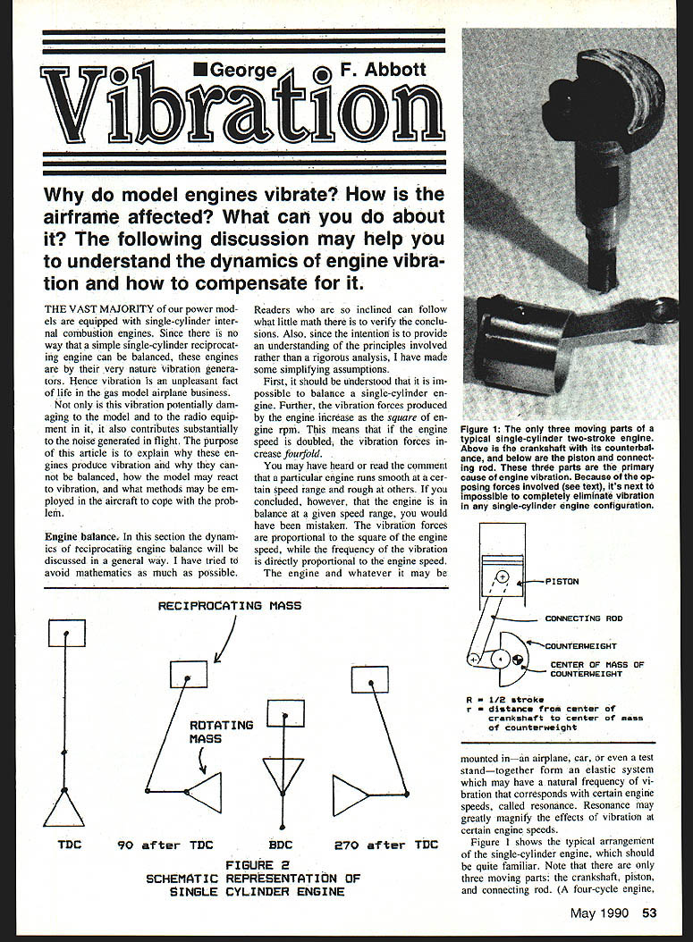
Figure 1 shows the typical arrangement of the single-cylinder engine. Note that there are only three moving parts: the crankshaft, piston, and connecting rod. (A four-cycle engine, of course, has a valve mechanism, but it isn't relevant to this discussion.) The crankshaft is the rotating part; the piston is the reciprocating part that travels back and forth in the cylinder in a straight line; the bottom end of the connecting rod travels a circular path while the top end follows the reciprocating motion of the piston.
As a general practice in engine balancing, the weight at the end of the connecting rod is balanced by an opposite weight mounted on the crankshaft; the resulting weights are assigned to the crankshaft and piston respectively. For this analysis we can ignore the weight of the connecting rod entirely without affecting the conclusions.
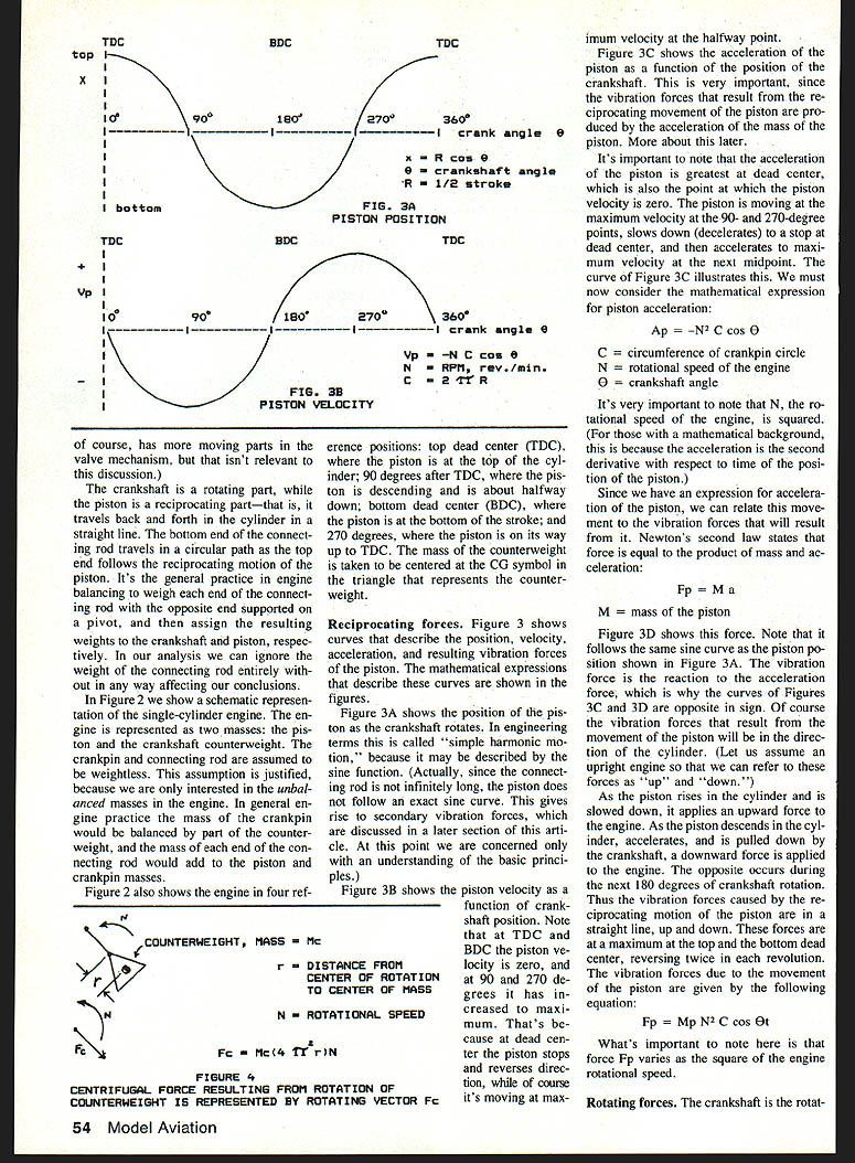
Figure 2 shows a schematic representation of a single-cylinder engine. The engine is represented by two masses: piston and counterweight. The crankpin and connecting rod are assumed weightless. This assumption is justified because in general engine practice the mass of the crankpin would be balanced as part of the counterweight and the mass at the end of the connecting rod would add to the piston/crankpin masses.
The positions shown are top dead center (TDC), 90 degrees after TDC where the piston is descending about halfway down, bottom dead center (BDC), and 270 degrees after TDC on its way up to TDC. The mass of the counterweight is taken centered. The symbol △ represents the counterweight.
Reciprocating forces
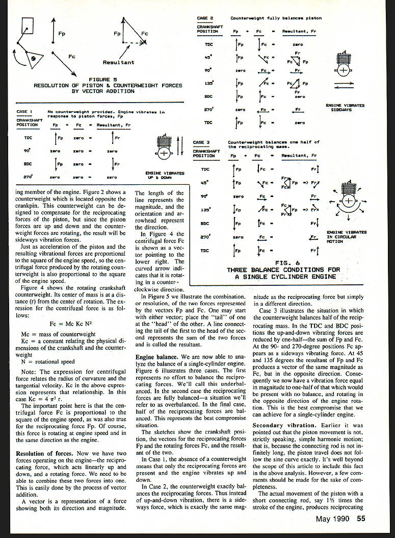
Figure 3 shows curves that describe the position, velocity, acceleration, and resulting vibration forces of the piston. The mathematical expressions that describe these curves are shown in the figures.
Figure 3A shows the position of the piston as the crankshaft rotates. In engineering terms this is called simple harmonic motion, because it may be described by the sine function. (Actually, since the connecting rod is not infinitely long, the piston does not follow an exact sine curve. This gives rise to secondary vibration forces, which are discussed in a later section. At this point we are concerned only with an understanding of the basic principles.)
Figure 3B shows the piston velocity as a function of crankshaft position. Note that at TDC and BDC the piston velocity is zero, and at 90 and 270 degrees it has increased to maximum. That's because at dead center the piston stops and reverses direction, while of course it's moving at maximum velocity at the halfway point.
Figure 3C shows the acceleration of the piston as a function of the position of the crankshaft. This is very important, since the vibration forces that result from the reciprocating movement of the piston are produced by the acceleration of the mass of the piston.
It's important to note that the acceleration of the piston is greatest at dead center, which is also the point at which the piston velocity is zero. The piston is moving at the maximum velocity at the 90- and 270-degree points, slows down (decelerates) to a stop at dead center, and then accelerates to maximum velocity at the next midpoint.
The mathematical expression for piston acceleration is:
Ap = -N^2 C cos θ
where
- C = circumference of crankpin circle
- N = rotational speed of the engine
- θ = crankshaft angle
It's very important to note that N, the rotational speed of the engine, is squared. (For those with a mathematical background, this is because acceleration is the second derivative with respect to time of the position of the piston.)
Since we have an expression for acceleration of the piston, we can relate this movement to the vibration forces that will result from it. Newton's second law states that force is equal to the product of mass and acceleration:
Fp = M Ap
where M is the mass of the piston.
Figure 3D shows this force. Note that it follows the same sine curve as the piston position shown in Figure 3A. The vibration force is the reaction to the acceleration force, which is why the curves of Figures 3C and 3D are opposite in sign. The vibration forces that result from the movement of the piston will be in the direction of the cylinder.
As the piston rises in the cylinder and is slowed down, it applies an upward force to the engine. As the piston descends in the cylinder, accelerates, and is pulled down by the crankshaft, a downward force is applied to the engine. The opposite occurs during the next 180 degrees of crankshaft rotation. Thus the vibration forces caused by the reciprocating motion of the piston are in a straight line, up and down. These forces are at a maximum at top and bottom dead center, reversing twice in each revolution.
The vibration forces due to the movement of the piston are given by:
Fp = Mp N^2 C cos θ
What's important to note here is that force Fp varies as the square of the engine rotational speed.
Rotating forces
The crankshaft is the rotating part. The counterweight mounted on the crankshaft produces a centrifugal force which may be represented by the rotating vector Fc (see Figure 4). This centrifugal force is proportional to the mass of the counterweight, the distance of its center of mass from the crankshaft center, and the square of the rotational speed.
The vertical component of this centrifugal force is Fc cos θ and therefore the vertical shaking force due to the counterweight is proportional to N^2 and varies as the cosine of the crank angle. By proper selection of the mass and angular position of the counterweight it is possible to partially balance the piston force. However, because the counterweight is rotating it also produces a horizontal shaking force which cannot be balanced by the piston, which produces only vertical reciprocating forces. Thus with a single-cylinder engine the best that can be achieved is partial balance of the reciprocating force in the vertical direction.
Figure 2 shows a counterweight located opposite the crankpin. This counterweight can be designed to compensate for the reciprocating forces of the piston, but since the piston forces are up and down and the counterweight forces are rotating, the result will be sideways vibration forces as well.
Just as acceleration of the piston and the resulting vibrational forces are proportional to the square of the engine speed, so the centrifugal force produced by the rotating counterweight is proportional to the square of the engine speed.
Figure 4 shows the rotating crankshaft counterweight. Its center of mass is at a distance r from the center of rotation. The expression for the centrifugal force is:
Fc = Mc Kc N^2
where
- Mc = mass of counterweight
- Kc = a constant relating the physical dimensions of the crankshaft and the counterweight
- N = rotational speed
Note: The expression for centrifugal force relates the radius of curvature and the tangential velocity. Kc in the above expression represents that relationship. In this case Kc = 4π^2 r.
The important point here is that the centrifugal force Fc is proportional to the square of the engine speed, as was also true for the reciprocating force Fp. Of course, this force is rotating at engine speed and in the same direction as the engine.
Resolution of forces
Now we have two forces operating on the engine — the reciprocating force, which acts linearly up and down, and a rotating force. We combine these two forces by vector addition.
A vector is a representation of a force showing both its direction and magnitude. The length of the line represents the magnitude, and the orientation and arrowhead represent the direction.
In Figure 4 the centrifugal force Fc is shown as a vector pointing to the lower right. The curved arrow indicates that it is rotating in a counterclockwise direction.
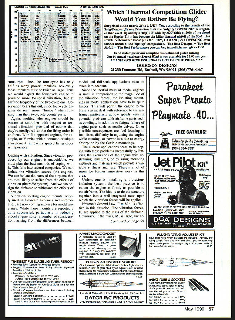
In Figure 5 we illustrate the combination, or resolution, of the two forces represented by the vectors Fp and Fc. One may start with either vector; place the tail of one at the head of the other. A line connecting the tail of the first to the head of the second represents the sum of the two forces and is called the resultant.
Engine balance (analysis)
We are now able to analyze the balance of a single-cylinder engine. Figure 6 illustrates three cases. The first represents no effort to balance the reciprocating forces (underbalanced). In the second case the reciprocating forces are fully balanced (overbalanced). In the final case half of the reciprocating forces are balanced. This represents the best compromise situation.
The sketches show the crankshaft position, the vectors for the reciprocating forces Fp and the rotating forces Fc, and the resultant of the two.
- Case 1: With no counterweight, only the reciprocating forces are present and the engine vibrates up and down.
- Case 2: A counterweight exactly balances the reciprocating forces. Instead of up-and-down vibration, there is a sideways force of the same magnitude as the reciprocating force but in a different direction.
- Case 3: The counterweight balances half of the reciprocating mass. At TDC and BDC the up-and-down vibrating forces are reduced by one-half — the sum of Fp and Fc. At 90 and 270 degrees Fc appears as a sideways vibrating force. At 45 and 135 degrees the resultant of Fp and Fc produces a vector of the same magnitude as Fc but in the opposite direction. Consequently there is a vibration force equal in magnitude to one-half of that which would be present with no balance, and rotating in the opposite direction of engine rotation.
Case 3 is the best compromise that can be achieved for a single-cylinder engine.
Secondary vibration
Earlier it was pointed out that the piston movement is not, strictly speaking, simple harmonic motion; because the connecting rod is not infinitely long, the piston travel does not follow the sine curve exactly. This gives rise to secondary vibration.
The actual movement of the piston with a short connecting rod — say 1½ times the stroke of the engine — produces reciprocating forces which include a substantial component at twice the engine speed. The resulting vibrations are called secondary vibrations. In the case of a connecting rod with a length of 1½ times the stroke, the secondary vibrations will be about one-third the force of the primary vibrations. Since it's desirable, both for engine compactness and to reduce reciprocating mass, to have the connecting rod as short as possible, secondary vibrations are a significant factor in engine balancing.
In some multiple-cylinder engines the secondaries can be balanced, while in others they cannot. For example, a six-cylinder in-line engine or a 90-degree V-8 may be in primary and secondary balance.
Multicylinder engines
A twin-cylinder engine with a two-throw crankshaft in which the pistons move in opposite directions should be largely vibration free. A practical problem with such engines, however, is that because of the two-throw crankshaft the cylinders are not in line with each other. This results in a twisting force, called a couple, which will create some vibration. Although such engines will be somewhat less than ideally balanced, the vibration encountered is usually low enough to be of little practical concern. Such an engine will be in primary, but not secondary, balance.
Also available is an opposed twin-cylinder engine with a single-throw crankshaft in which the pistons both move in the same direction—an arrangement which offers no vibration advantage.
Torsional vibration
In previous sections we discussed vibration caused by the rotating and reciprocating masses of the engine. Another type of vibration results from the way the engine produces its power. Engine power is transmitted in a series of impulses—the force is produced only during the power stroke. The power of the engine is delivered to the propeller (or whatever load the engine is driving) as torque, which is a twisting force applied by the crankshaft.
In addition to producing torque, the engine must also receive torque as an input in order to carry through the compression stroke. Thus engines must have a flywheel to store up the energy produced by the power stroke so that some may be returned for the compression stroke, as well as to smooth out the power pulses. In aircraft engines the propeller serves as a flywheel.
Vibration due to torque is called torsional vibration. This twisting type of vibration is produced along the axis of the crankshaft at a frequency related to the rpm of the engine. Figure 7A illustrates this for a two-cycle engine. At top dead center (TDC) we see a large pulse of torque which is the power stroke. This is followed by the transfer period lasting about 120 degrees, or a third of the rotation of the crankshaft, during which there is no torque. During the transfer period the ports are open, and the cylinder is being scavenged of burned gases and charged with fresh fuel/air mixture. When the ports close the compression stroke commences, and we see a pulse of torque in the opposite direction to the power stroke. The cylinder fires, initiates another power pulse, and the process repeats.
Thus in addition to the vibration created by the imbalance of its moving parts, the engine is also producing torsional vibration. As many modelers are already well aware, torsional vibration may be very damaging to the airframe.
As Figure 7B illustrates, in four-cycle engines the power stroke occurs every other revolution. If a two-cycle and a four-cycle engine each produce the same power at the same speed, the four-cycle has only half as many power impulses, so those impulses must be about twice as large. Thus we would expect the four-cycle engine to produce more torsional vibration, but at half the frequency of the two-cycle one. Observation bears this out: four-cycle engines do seem more "lumpy" when running than their two-cycle counterparts.
Again, multicylinder engines should be somewhat smoother with respect to torsional vibration, provided the firing order is uniform. With flat-opposed engines, for example, or V-twins with a common crankpin arrangement, an evenly spaced firing order may be impossible and torsional effects persist.
Coping with vibration
Since vibration produced by our engines is unavoidable, we must plan methods of coping with it. This falls into several categories:
- Isolate the vibration source (the engine).
- Isolate the parts of the airplane that are most likely to suffer from the effects of vibration (the radio system).
- Design the airframe to withstand the effects of vibration.
Vibration-isolating engine mounts, widely used in full-scale airplanes and automobiles, are now coming into use for model airplanes. While these mounts are reportedly quite successful, particularly in reducing model engine noise, a number of considerations arising from the differences between model and full-scale applications must be taken into account.
Since the inertial mass of model engines is small in comparison to the magnitude of the vibration forces, the isolating mountings in model applications have to be quite limber. This will permit the engine to vibrate a great deal with reference to the airframe, particularly at low speeds, causing potential problems with airframe parts such as cowlings, in addition to fatigue failure of engine parts such as needle valves. Other possible consequences are fuel foaming in fuel lines, difficulty in adjusting the engine while running, or power loss due to energy absorption by the flexible mountings.
Current applications seem to cope with these problems by limiting the excursions of the engine with straining structures, or by using mounting methods and materials that provide variable stiffness and rate. There's a lot of room for further innovative work in this area.
Unless one is installing a vibration-isolation system, the best practice is to mount the engine as firmly as possible to the airframe. The idea is to tie the structure together into a well-integrated mass upon which the vibration forces will be applied.
Newton's second law, F = M a, is effective in this situation. The vibration forces F are applied to the mass of the airframe. Obviously, if the mass M is large, the acceleration a will be less. Thus a very light airframe will be more subject to vibration effects.
A corollary is the recommendation that the entire airframe be constructed as rigidly as possible. There should be little or no relative motion between various parts of the structure. This will reduce problems with fatigue and wearout, and will also prevent secondary vibrations which occur when parts of the airframe rattle against each other.
The solution is to isolate sensitive and critical parts, particularly the radio, against damaging vibration. This is generally done by wrapping the receiver and battery in sponge rubber and mounting the servos through rubber grommets. The method seems to work quite well, as long as the sponge rubber wrapping is kept as loose as possible and the servos are not screwed down too tightly.
It's important to understand the modes of vibration that will be found in the airframe. Consider the entire airplane as a freely suspended body with three degrees of freedom—that is, it is free to move in any direction without outside restraint. (Aerodynamic forces do impose restraints on movement, but these may be ignored for this analysis.) The vibration forces are applied to the airplane at the engine, usually in the front of the craft. The plane will respond to this input by vibrating about the center of mass, or center of gravity (CG).
Figure 8 shows that the amplitude of vibration will be minimal at the CG and increase with distance from that point. Thus the most vibration-sensitive equipment—the receiver and servos in particular—should be located as close as possible to the CG.
When it's necessary to place electronic components at a distance from the CG—for example, situating the battery pack forward for purposes of balance—they should be carefully packed in vibration-isolating rubber. Since it's almost always positioned close to the engine, the fuel tank is subject to severe vibrations.
The practice of placing servos at the tail or near the ailerons in Giant Scale models should be carefully weighed, as it subjects them to greater vibration than locations near the CG. Those chain-saw engines produce some awesome vibration forces. Torsional vibration places severe stress on the main surfaces and the aft fuselage. In Giant Scale models using their chain-saw-type or large four-cycle engines, it's a good idea to use brace wires between the fin, stabilizer, and fuselage. Strengthening the aft fuselage helps too.
A properly balanced propeller also helps minimize vibration. Any imbalance of the propeller will cause substantial vibration and should be avoided. If one knew for certain that a particular engine was underbalanced or overbalanced, it might be possible to reduce the overall vibration by installing an unbalanced propeller. However, that's probably not the most practical approach.
As long as the single-cylinder reciprocating engine remains the predominant power plant for model airplanes, vibration will remain a constant concern. We can best cope with the problem by building solid airframe structures and providing vibration isolation for sensitive components such as radios. As technology improves, vibration-isolating engine mountings seem very promising.
Transcribed from original scans by AI. Minor OCR errors may remain.

