
Voltage
by Cal Orr
Receiver voltage
Even the most robust radio systems are worthless without a good, clean power supply.
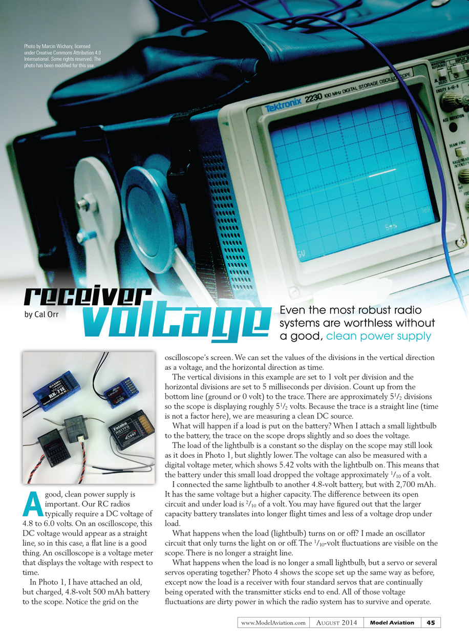
A good, clean power supply is important. Our RC radios typically require a DC voltage of 4.8 to 6.0 volts. On an oscilloscope, this DC voltage appears as a straight line — in this case, a flat line is a good thing. An oscilloscope is a voltage meter that displays voltage with respect to time.
In Photo 1 I attached an old but charged 4.8-volt, 500 mAh battery to the scope. Notice the grid on the oscilloscope screen. We can set the values of the divisions in the vertical direction as voltage and the horizontal direction as time.
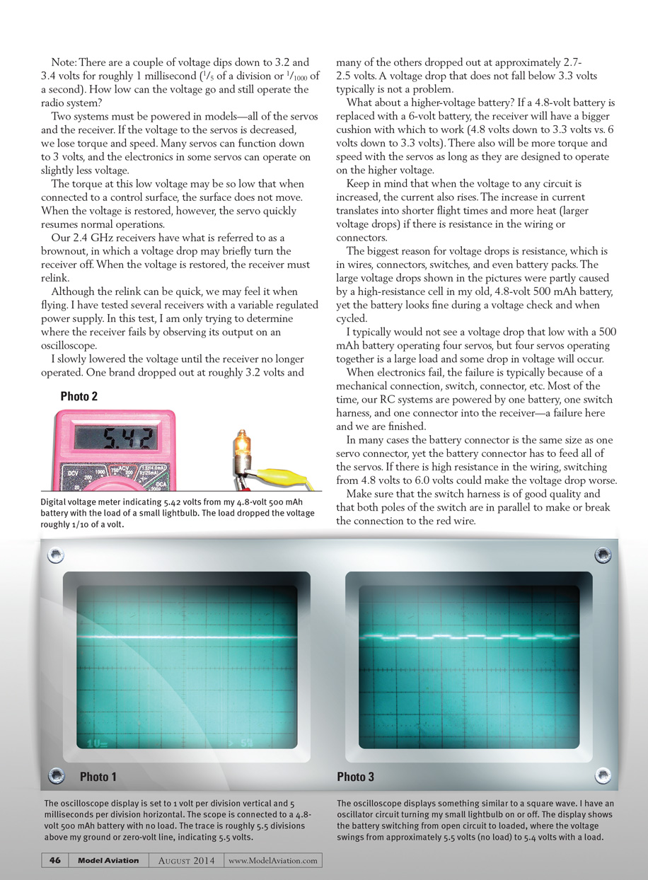
The vertical divisions in this example are set to 1 volt per division and the horizontal divisions are set to 5 milliseconds per division. Count up from the bottom line (ground or 0 volt) to the trace. There are approximately 5.5 divisions, so the scope is displaying roughly 5.5 volts. Because the trace is a straight line (time is not a factor here), we are measuring a clean DC source.
What happens if a load is put on the battery? When I attach a small lightbulb to the battery, the trace on the scope drops slightly and so does the voltage. The load of the lightbulb is constant, so the display on the scope may still look like Photo 1, but slightly lower. The voltage can also be measured with a digital voltmeter, which shows 5.42 volts with the lightbulb on. This means the battery under this small load dropped the voltage approximately 0.1 volt.
I connected the same lightbulb to another 4.8-volt battery, but with 2,700 mAh. It has the same nominal voltage but higher capacity. The difference between its open-circuit voltage and under-load voltage is 0.2 volt. The larger capacity battery translates into longer flight times and less of a voltage drop under load.
What happens when the load (the lightbulb) turns on or off? I made an oscillator circuit that only turns the light on or off. The 0.1-volt fluctuations are visible on the scope — there is no longer a straight line.
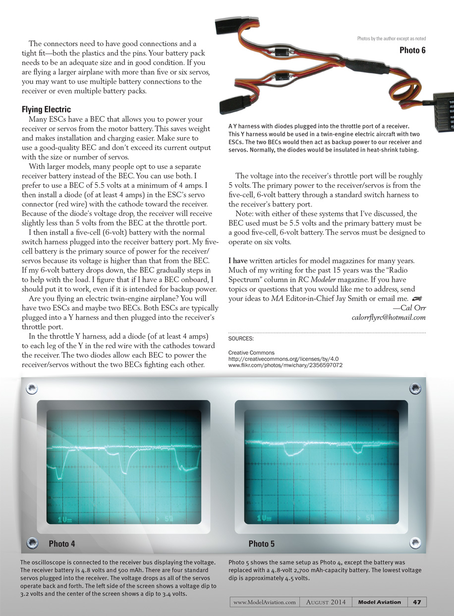
What happens when the load is no longer a small lightbulb but a servo or several servos operating together? Photo 4 shows the scope set up the same way as before, except now the load is a receiver with four standard servos that are continually being operated with the transmitter sticks end to end. All of those voltage fluctuations are dirty power that the radio system must survive and operate through.
Note: There are a couple of voltage dips down to 3.2 and 3.4 volts for roughly 1 millisecond (1/5 of a division, or 1/1000 of a second). How low can the voltage go and still allow the radio system to operate?
Two systems must be powered in models — all of the servos and the receiver. If the voltage to the servos is decreased, we lose torque and speed. Many servos can function down to about 3 volts, and the electronics in some servos operate on slightly less voltage. The torque at that low voltage may be so low that, when connected to a control surface, the surface does not move. When the voltage is restored, however, the servo quickly resumes normal operation.
Our 2.4 GHz receivers have what is referred to as a brownout, in which a voltage drop may briefly turn the receiver off. When the voltage is restored, the receiver must relink. Although the relink can be quick, we may feel it when flying.
I have tested several receivers with a variable regulated power supply. In this test I was trying to determine where the receiver fails by observing its output on an oscilloscope. I slowly lowered the voltage until the receiver no longer operated. One brand dropped out at roughly 3.2 volts and many of the others dropped out at approximately 2.7–2.5 volts. A voltage drop that does not fall below about 3.3 volts typically is not a problem.
What about a higher-voltage battery? If a 4.8-volt battery is replaced with a 6-volt battery, the receiver has a bigger cushion (4.8 V down to 3.3 V vs. 6.0 V down to 3.3 V). There will also be more torque and speed with servos, as long as they are designed to operate on the higher voltage.
Keep in mind that when the voltage to any circuit is increased, the current also rises. The increase in current translates into shorter flight times and more heat (larger voltage drops) if there is resistance in the wiring or connectors.
The biggest reason for voltage drops is resistance — in wires, connectors, switches, and even battery cells. The large voltage drops shown in the pictures were partly caused by a high-resistance cell in my old 4.8-volt, 500 mAh battery, yet the battery looked fine during a static voltage check and when cycled.
I typically would not see a voltage drop that low with a 500 mAh battery operating four servos, but four servos operating together is a large load and some drop in voltage will occur.
When electronics fail, the failure is typically due to a mechanical connection — switch, connector, etc. Most of the time our RC systems are powered by one battery, one switch harness, and one connector into the receiver. A failure there ends the flight.
- Common causes of voltage drop and failure:
- High resistance in wiring
- Poor connectors or loose pins
- Faulty switch harness or single-pole switching
- A weak or high-resistance cell in a battery pack
Make sure that the switch harness is of good quality and that both poles of the switch are used in parallel to make or break the connection to the red wire. The connectors need to have good mechanical fit — both the plastics and the pins. Your battery pack needs to be an adequate size and in good condition. If you are flying a larger airplane with more than five or six servos, consider using multiple battery connections to the receiver or even multiple battery packs.
Flying Electric
Many ESCs have a BEC that allows you to power your receiver or servos from the motor battery. This saves weight and makes installation and charging easier. Make sure to use a good-quality BEC and don't exceed its current output with the size or number of servos.
With larger models, many people opt to use a separate receiver battery instead of relying solely on the BEC. You can use both. I prefer to use a BEC rated at 5.5 volts minimum or 4 amps, and I then install a diode (at least 4 amps) in the ESC’s servo connector (red wire) with the cathode toward the receiver. Because of the diode’s voltage drop, the receiver will receive slightly less than 5 volts from the BEC at the throttle port.
I then install a five-cell (6-volt) battery with the normal switch harness plugged into the receiver battery port. My five-cell battery is the primary source of power for the receiver/servos because its voltage is higher than that from the BEC. If my 6-volt battery drops, the BEC gradually steps in to help with the load. If I have a BEC onboard, I prefer to put it to work as backup power.
Are you flying an electric twin-engine airplane? You will have two ESCs and maybe two BECs. Both ESCs are typically plugged into a Y harness and then into the receiver’s throttle port.
- In the throttle Y harness, add a diode (at least 4 amps) to each leg of the Y in the red wire with the cathodes toward the receiver. The two diodes allow each BEC to power the receiver/servos without the BECs fighting each other.
- The voltage into the receiver’s throttle port will be roughly 5 volts. The primary power to the receiver/servos remains the five-cell, 6-volt battery through a standard switch harness to the receiver’s battery port.
Note: With either system described above, the BEC used should be 5.5 volts and the primary battery a good five-cell, 6-volt battery. The servos must be designed to operate on six volts.
I have written articles for model magazines for many years. Much of my writing for the past 15 years was the "Radio Spectrum" column in RC Modeler magazine. If you have topics or questions you would like me to address, send your ideas to MA Editor-in-Chief Jay Smith or email me.
— Cal Orr [email protected]
Transcribed from original scans by AI. Minor OCR errors may remain.

