
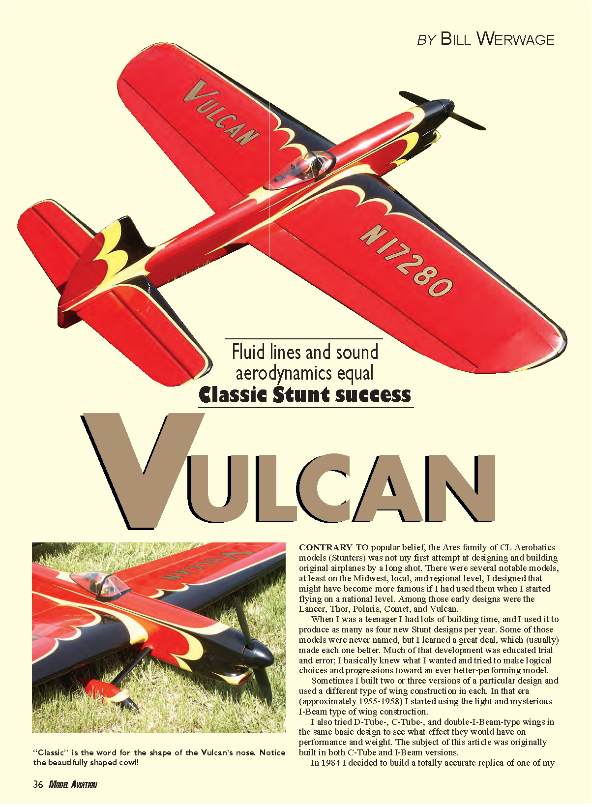
VULCAN
By Bill Werwage
Contrary to popular belief, the Ares family of CL Aerobatics models (Stunters) was not my first attempt at designing and building original airplanes. As a teenager I designed several notable models—Lancer, Thor, Polaris, Comet, and Vulcan—and produced as many as four new Stunt designs per year in the mid-1950s. Some were unnamed, but each taught me something and usually improved the next design. Much of that development was educated trial and error and logical progression.
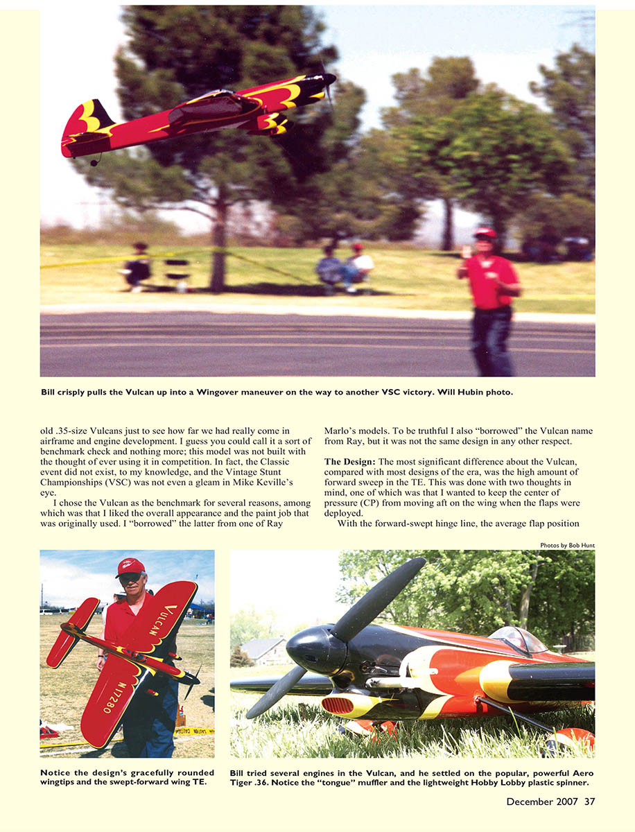
The Vulcan was one of those early designs. I originally built it in both C-Tube and I-Beam wing versions. In 1984 I built a totally accurate replica of a .35-size Vulcan as a benchmark to see how airframe and engine development had progressed. The replica was not built for competition initially, but the Vulcan’s appearance and paint scheme (borrowed from Ray Marlo) and the name (also borrowed from Ray) made it a natural candidate for restoration.
The Design
The most significant difference between the Vulcan and most designs of the era is the pronounced forward sweep in the trailing-edge (TE) hinge line. This was done for two main reasons:
- To limit aft movement of the center of pressure (CP) when the flaps are deployed. With a forward-swept hinge line the average flap position is ahead of where it would be on a straight-hinge model. Deployed flaps therefore move the CP less far aft, reducing overstabilization and preventing the model from becoming unduly nose-heavy with flaps down. The result is dramatically reduced stick pressure in the handle, especially in high wind.
- To effectively lengthen the tail moment. The moment is measured from the average flap position relative to the stabilizer/elevator hinge line.
The Vulcan was designed with larger-than-average flaps and a thin-tip airfoil section. The combination produced ample lift, easy turning in wind, and reduced drag because of the thinner average airfoil thickness—important in an era of limited engine power.
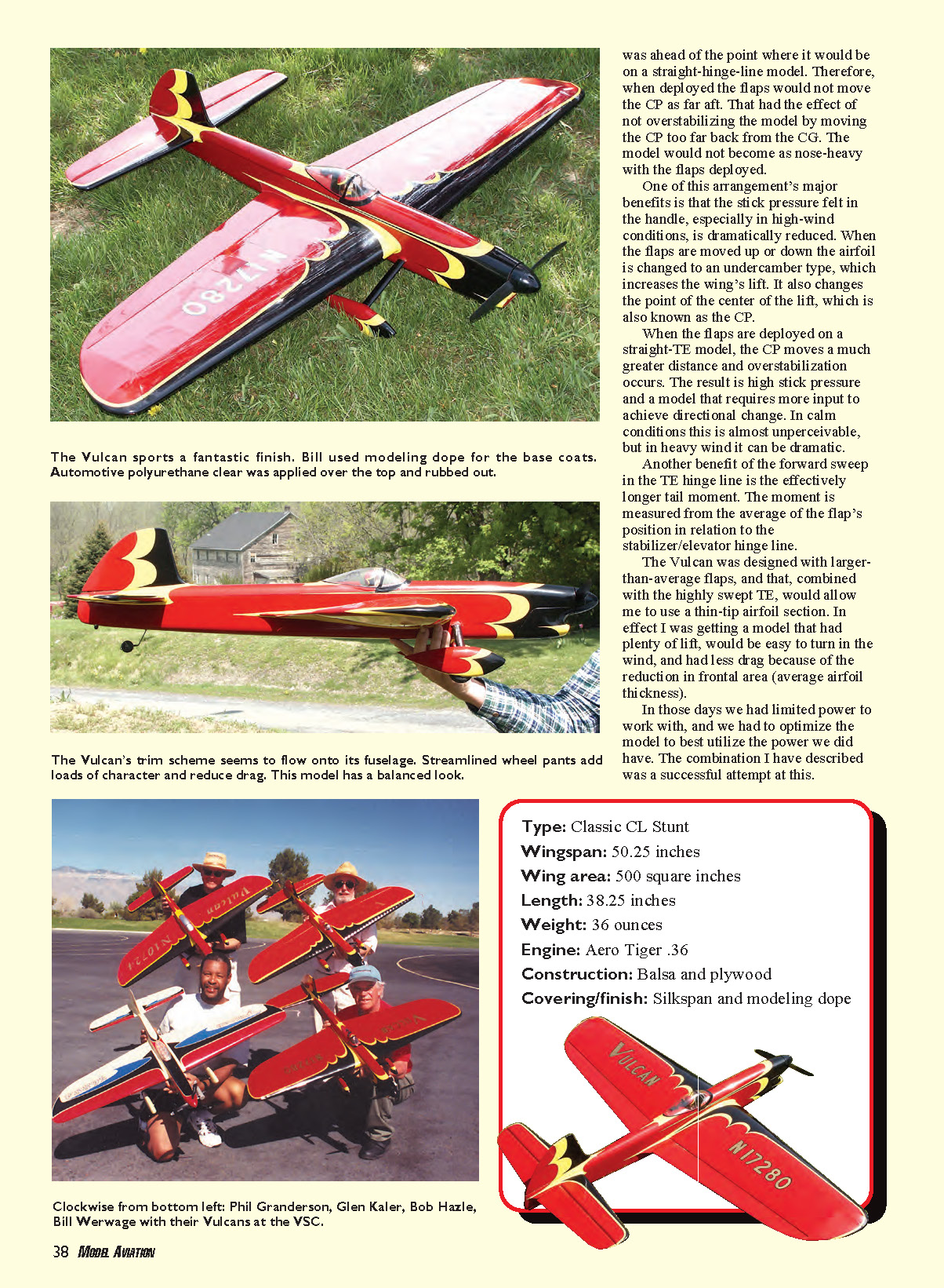
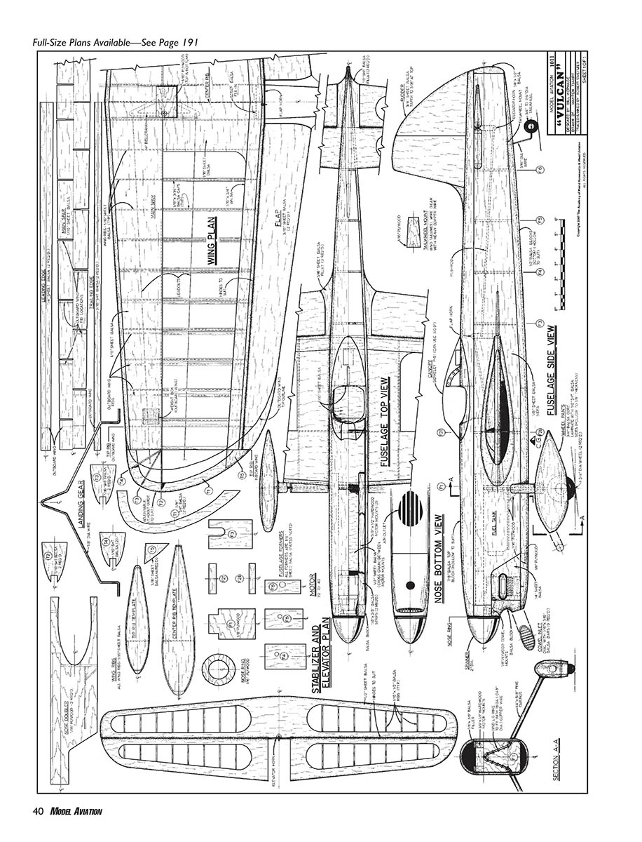
Specifications
- Type: Classic CL Stunt
- Wingspan: 50.25 inches
- Wing area: 491.24 square inches (commonly rounded to ~500 sq in)
- Length: 38.25 inches
- Weight: 36 ounces
- Original engine: Fox .35 (original); replica used various modern engines in testing
- Construction: Balsa and plywood
- Covering/finish: Silkspan (Japanese tissue) and modeling dope
The original Vulcan flew on 60 feet of .015 cable with a Fox .35 and a 10 x 5 Y&O wooden prop. The C-Tube and I-Beam variants flew very similarly.
Engines, power and modern considerations
When I flew the replica, the original-era engines proved underpowered in wind, so I experimented with more modern engines:
- Webra .28 with the same 10 x 5 prop and slightly longer .012 solid lines — an improvement.
- Lightened SuperTiger .46 with an 11 x 5 Rev-Up prop, .014 solid lines and 63-foot lines — a dramatic performance boost, but high vibration risk for the small airframe.
- O.S. .32 — well balanced and good, but I still wanted more power.
Randy Smith of Aero Products suggested the new Thunder Tiger ABC .36 (aluminum ABC sleeve/piston, dual ball bearings). It ran well for many fliers but was heavier than the original Fox .35 by about 2.0–2.5 ounces. Randy then produced a custom aluminum-chrome (AAC) piston and liner and a lighter sleeve to our specifications, producing an "Aero Tiger" AAC .36 that was about 0.7 ounce lighter than the stock ABC version and ran great.
Modern Schnuerle-port engines produce power at higher rpm than loop-scavenged engines of the past and therefore require less pitch. Many setups now run pitches in the 3.6–4.0 inch range, compared with 5.0–6.0 inches in older setups. Lower-pitch props let the airplane turn more easily, which helps offset extra nose weight from heavier modern engines and accessories.
Other modern-weight considerations:
- Longer two-lap-between-maneuver formats require larger fuel loads.
- Mufflers, carbon-fiber props, larger crankshafts and robust ABC/AAC construction add nose weight.
- Countermeasures include lightweight plastic tanks (mounted as far aft as practical), lightweight plastic/composite spinners (properly machined and balanced), and extension shafts in extreme cases.
The replica Vulcan ultimately proved successful in competition. I started flying it in Classic and Vintage events; at the 1994 Vintage Stunt Championships (VSC) I won with the Vulcan design for the first time in 38 years. Since then, I have flown the Vulcan, the 1959 Ares, and the 1962 Ares at the VSC and have been fortunate to win multiple times. The Vulcan captured four VSC victories; the last three were with the Aero Tiger .36. The model also won the Classic event at the Nats in 1996. (Editor's note: Bill has added additional VSC wins since this article was written.)
CONSTRUCTION
Building the Vulcan is similar to building any Stunt model of that era. It is relatively small—around a 50-inch span with approximately 491.24 square inches of wing—so weight control is critical. Use light materials chosen for their intended function: firm wood for wing spars, softer balsa for fuselage top and bottom blocks.
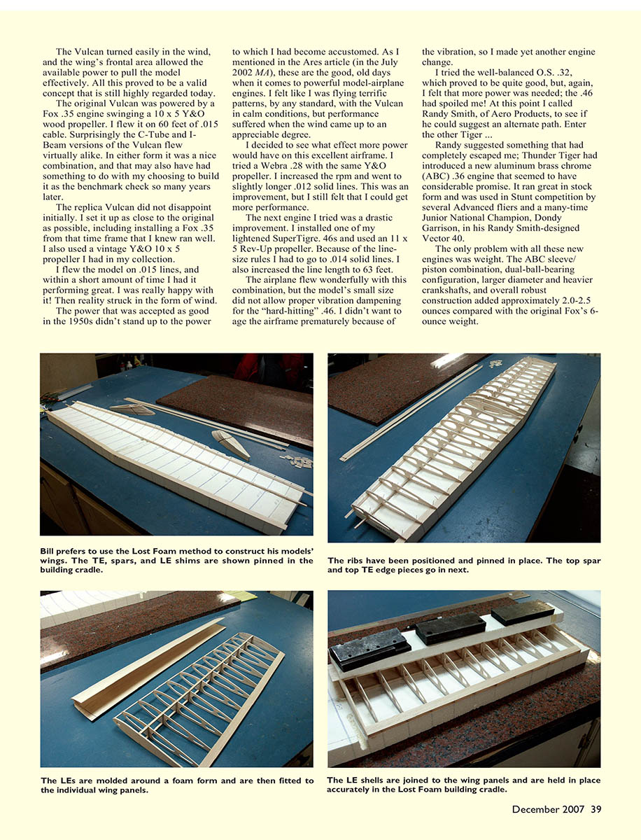
The C-Tube version described here is the variation I built as a replica in 1984. While there are many ways to build a C-Tube wing, the Lost Foam wing-building system is the easiest and most accurate method. Lost Foam keys the outside shape of the wing and allows precise molding and installation of leading edges (LEs), guaranteeing a consistent LE radius—something extremely important to performance.
Lost Foam wing systems and LE mold bucks for the Vulcan are available from Robin's View Productions, which also sells comprehensive videos explaining the Lost Foam method. I recommend studying them before you begin construction.
Flaps and hinges
A common question is whether a normal, straight control horn will bind on a forward-swept hinge line. If you follow these rules, binding is negligible:
- Sand a flat on the rear face of the TE that is exactly 90° to the wing centerline (viewed from above).
- Keep the lengths of the horn arms from the upright at the center equal.
- The horn's pivot point must be centered and aligned with the flap's hinge center.
- Keep flap-horn length as short as possible.
I used 3/16-inch-thick flaps on the plans when I could find optimum firm, light "C"-grain wood. If that stock is not available, use light 1/4-inch stock.
I prefer cloth hinges on Classic-type models because they provide a light, well-sealed hinge line. If you use pinned hinges you will probably have to seal the hinge line with tape unless the gap is kept to a minimum.
The plans included with this article are detailed. Warren Trisait produced a great set of pencil drawings from my original etchings, and Bob Sweitzer did an outstanding job tracing and inking them. There are abundant building notes on the plans; anyone familiar with this type of model should be able to reproduce it after studying them.
Finish
I covered the Vulcan with Japanese tissue and applied the base and color coats using modeling dope. I mix color by using auto-paint toners: 1/3 toner to 2/3 clear dope, then thin and spray. Auto toners offer a wide range of colors and generally cover better than dopes alone. The final topcoat is catalyzed polyurethane clear.
Safety note: catalyzed polyurethane clears are extremely toxic. Use a modern spray booth with an effective exhaust and at least a good charcoal respirator, or use a quality clear modeling dope as an alternative (still use exhaust and a respirator).
Built light, straight, and powered properly, the Vulcan will reward you with many satisfying flights—and perhaps a few trophies.
Bill Werwage
Sources
- Aero Products
(678) 407-9376 www.aeroproduct.net
- Robin's View Productions
(610) 746-0106 Email: [email protected]
Transcribed from original scans by AI. Minor OCR errors may remain.

