
Wing Ding II
by Les Garber
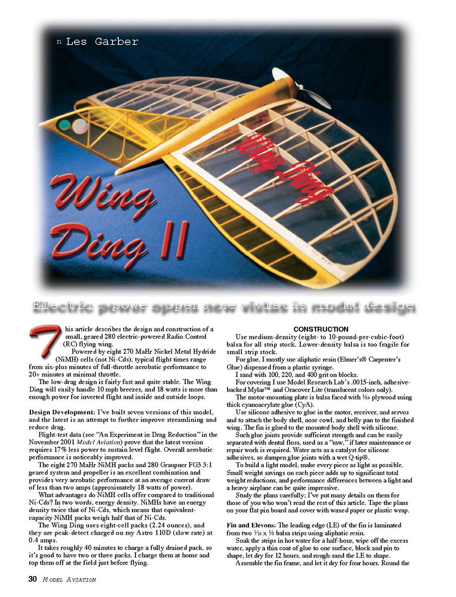
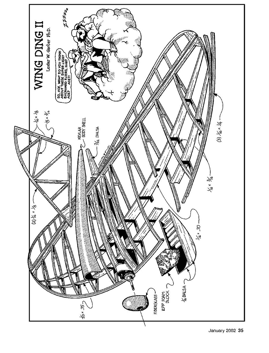
This article describes the design and construction of a small, geared 280 electric-powered Radio Control (RC) flying wing.
Powered by eight 270 mAh Nickel Metal Hydride (NiMH) cells (not Ni-Cads), typical flight times range from six-plus minutes of full-throttle aerobatic performance to 20+ minutes at minimal throttle.
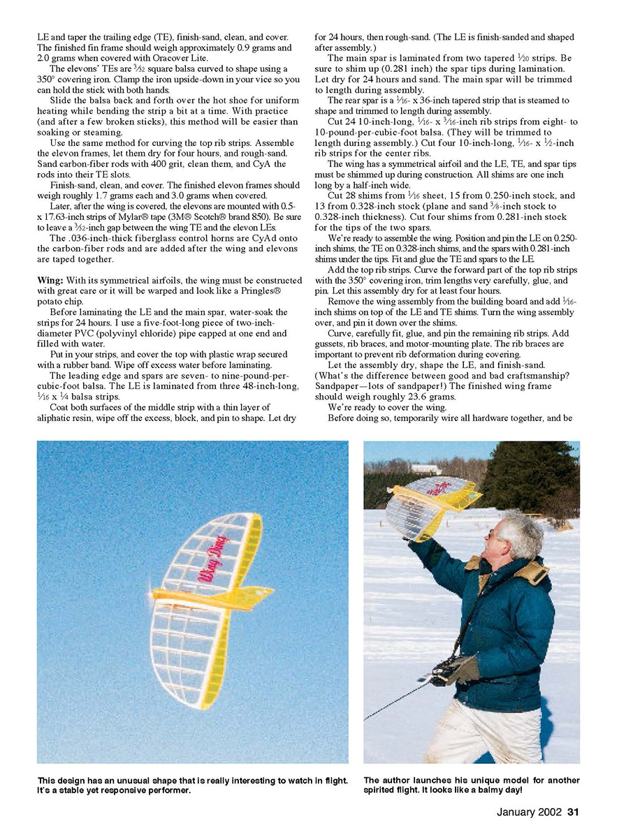
The low-drag design is fairly fast and quite stable. The Wing Ding will easily handle 10 mph breezes, and 18 watts is more than enough power for inverted flight and inside and outside loops.
Design Development: I've built seven versions of this model, and the latest is an attempt to further improve streamlining and reduce drag.
Flight-test data (see "An Experiment in Drag Reduction" in the November 2001 Model Aviation) prove that the latest version requires 17% less power to sustain level flight. Overall aerobatic performance is noticeably improved.
The eight 270 mAh NiMH packs and 280 Graupner FG3 3:1 geared system and propeller is an excellent combination and provides very aerobatic performance at an average current draw of less than two amps (approximately 18 watts of power).
What advantages do NiMH cells offer compared to traditional Ni-Cds? In two words, energy density. NiMHs have an energy density twice that of Ni-Cds, which means that equivalent-capacity NiMH packs weigh half that of Ni-Cds.
The Wing Ding uses eight-cell packs (2.24 ounces), and they are peak-detect charged on my Astro 110D (slow rate) at 0.4 amps.
It takes roughly 40 minutes to charge a fully drained pack, so it's good to have two or three packs. I charge them at home and top them off at the field just before flying.
CONSTRUCTION
Use medium-density (eight- to 10-pound-per-cubic-foot) balsa for all strip stock. Lower-density balsa is too fragile for small strip stock.
For glue, I mostly use aliphatic resin (Elmer's® Carpenter's Glue) dispensed from a plastic syringe.
I sand with 100, 220, and 400 grit on blocks.
For covering I use Model Research Lab's .0015-inch, adhesive-backed Mylar™ and Oracover Lite (translucent colors only).
The motor-mounting plate is balsa faced with 1/64 plywood using thick cyanoacrylate glue (CA).
Use silicone adhesive to glue in the motor, receiver, and servos and to attach the body shell, nose cowl, and belly pan to the finished wing. The fin is glued to the mounted body shell with silicone.
Such glued joints provide sufficient strength and can be easily separated with dental floss, used as a "saw," if later maintenance or repair work is required. Water acts as a catalyst for silicone adhesives, so dampen glue joints with wet Q-tip®.
To build a light model, make every piece as light as possible. Small weight savings on each piece adds up to significant total weight reductions, and performance differences between a light and a heavy airplane can be quite impressive.
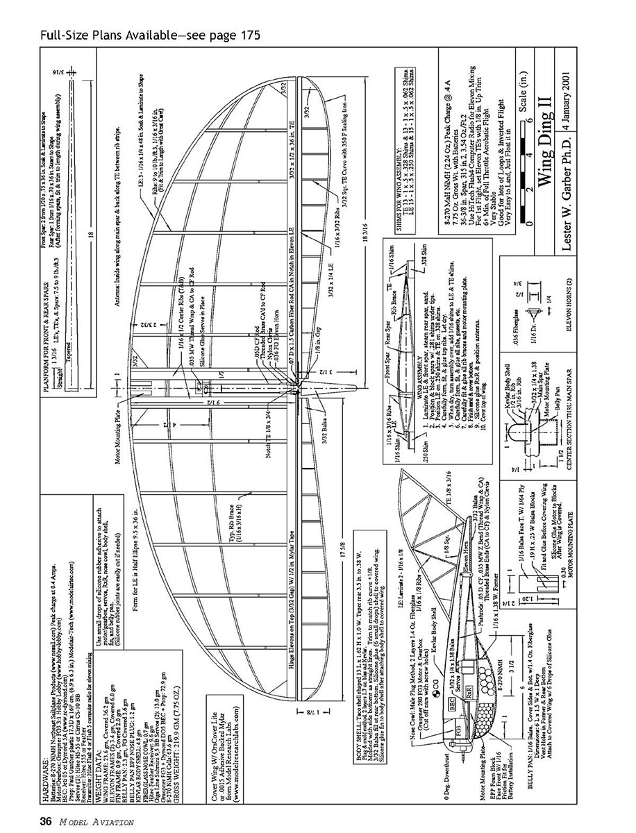
Study the plans carefully; I've put many details on them for those of you who won't read the rest of this article. Tape the plans on your flat pin board and cover with waxed paper or plastic wrap.
Fin and Elevons
The leading edge (LE) of the fin is laminated from two 1/16 x 3/4 balsa strips using aliphatic resin.
Soak the strips in hot water for a half-hour, wipe off the excess water, apply a thin coat of glue to one surface, block and pin to shape, let dry for 12 hours, and rough-sand the LE to shape.
Assemble the fin frame, and let it dry for four hours. Round the LE and taper the trailing edge (TE), finish-sand, clean, and cover. The finished fin frame should weigh approximately 0.9 grams and 2.0 grams when covered with Oracover Lite.
The elevons' TEs are 3/32 square balsa curved to shape using a 350° covering iron. Clamp the iron upside-down in your vice so you can hold the stick with both hands.
Slide the balsa back and forth over the hot shoe for uniform heating while bending the strip a bit at a time. With practice (and after a few broken sticks), this method will be easier than soaking or steaming.
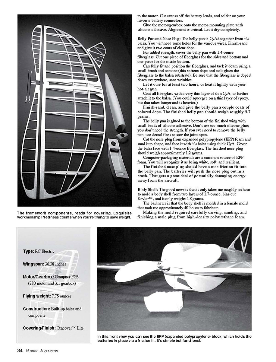
Use the same method for curving the top rib strips. Assemble the elevon frames, let them dry for four hours, and rough-sand. Sand carbon-fiber rods with 400 grit, clean them, and CyA the rods into their TE slots.
Finish-sand, clean, and cover. The finished elevon frames should weigh roughly 1.7 grams each and 3.0 grams when covered.
Later, after the wing is covered, the elevons are mounted with 0.5- x 17.63-inch strips of Mylar® tape (3M® Scotch® brand 850). Be sure to leave a 3/32-inch gap between the wing TE and the elevon LEs.
The .036-inch-thick fiberglass control horns are CyA'd onto the carbon-fiber rods and are added after the wing and elevons are taped together.
Wing
With its symmetrical airfoils, the wing must be constructed with great care or it will be warped and look like a Pringles® potato chip.
Before laminating the LE and the main spar, water-soak the strips for 24 hours. I use a five-foot-long piece of two-inch-diameter PVC (polyvinyl chloride) pipe capped at one end and filled with water.
Put in your strips, and cover the top with plastic wrap secured with a rubber band. Wipe off excess water before laminating.
The leading edge and spars are seven- to nine-pound-per-cubic-foot balsa. The LE is laminated from three 48-inch-long, 1/16 x 1/4 balsa strips.
Coat both surfaces of the middle strip with a thin layer of aliphatic resin, wipe off the excess, block, and pin to shape. Let dry for 24 hours, then rough-sand. (The LE is finish-sanded and shaped after assembly.)
The main spar is laminated from two tapered 1/8 strips. Be sure to shim up (0.281 inch) the spar tips during lamination. Let dry for 24 hours and sand. The main spar will be trimmed to length during assembly.
The rear spar is a 1/16- x 3/16-inch tapered strip that is steamed to shape and trimmed to length during assembly.
Cut 24 10-inch-long, 1/16- x 3/16-inch rib strips from eight- to 10-pound-per-cubic-foot balsa. (They will be trimmed to length during assembly.) Cut four 10-inch-long, 1/16- x 1/2-inch rib strips for the center ribs.
The wing has a symmetrical airfoil and the LE, TE, and spar tips must be shimmed up during construction. All shims are one inch long by a half-inch wide.
Cut 28 shims from 1/16 sheet, 15 from 0.250-inch stock, and 13 from 0.328-inch stock (plane and sand 3/8-inch stock to 0.328-inch thickness). Cut four shims from 0.281-inch stock for the tips of the two spars.
We're ready to assemble the wing. Position and pin the LE on 0.250-inch shims, the TE on 0.328-inch shims, and the spars with 0.281-inch shims under the tips. Fit and glue the TE and spars to the LE.
Add the top rib strips. Curve the forward part of the top rib strips with the 350° covering iron, trim lengths very carefully, glue, and pin. Let this assembly dry for at least four hours.
Remove the wing assembly from the building board and add 1/16-inch shims on top of the LE and TE shims. Turn the wing assembly over, and pin it down over the shims.
Curve, carefully fit, glue, and pin the remaining rib strips. Add gussets, rib braces, and motor-mounting plate. The rib braces are important to prevent rib deformation during covering.
Let the assembly dry, shape the LE, and finish-sand. (What's the difference between good and bad craftsmanship? Sandpaper—lots of sandpaper!) The finished wing frame should weigh roughly 23.6 grams.
We're ready to cover the wing.
Before doing so, temporarily wire all hardware together, and be sure that everything works and servos are moving in the right direction. To make a neater assembly and save a bit of weight, I cut off excess wire (servo leads, etc.) and resolder.
Nothing looks uglier than a long antenna wire dragging behind a beautiful airplane; I put the antenna inside the covered wing. Following is how I do it.
Cover the bottom of the wing (attach covering to the LE, the TE, and all ribs).
Position the receiver behind the front spar. Run antenna through a small hole (burned through with a hot needle) in the center of the main spar, along the front of the spar, out to the wingtip, back through small holes in the two spar tips to the TE, then back along the TE between the upper and lower rib strips.
Hold the antenna in place with friction or with some 1/16 scraps CyA'd in.
Cover the top of the wing, and cut out the top covering over the center-section. Now we are ready to add the elevons.
Wing and Elevon Assembly
Pin the covered wing and elevons to your building board with a 3/32-inch gap, and join with a 1/2- x 17.63-inch strip of Mylar™ tape (3M® Scotch® brand 850) for each elevon. The Mylar™ tape is on the top surfaces only.
After the elevons have been taped to the wing, carefully position and glue the .036-inch-thick fiberglass elevon control horns onto the carbon-fiber rods with thick CyA.
These are critical joints, so be sure to sand and clean the rods before fitting and gluing. For added strength, build up a fillet between the control horns and rods using baking soda and thin CyA.
Component Installation
Temporarily wire together the servos, receiver, speed controller, and motor. Before doing any permanent installations, double check to make sure everything works.
Trial-fit the servos, and plug them into the receiver. Using silicone adhesive and small clamps, position and glue the servos and let them cure overnight.
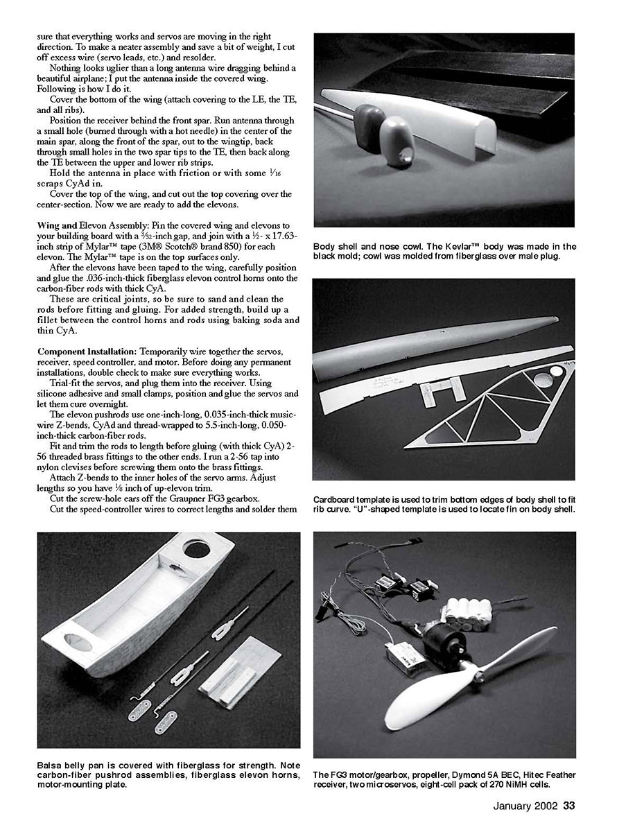
The elevon pushrods use one-inch-long, 0.035-inch-thick music-wire Z-bends, CyA'd and thread-wrapped to 5.5-inch-long, 0.050-inch-thick carbon-fiber rods.
Fit and trim the rods to length before gluing (with thick CyA) 2-56 threaded brass fittings to the other ends. I run a 2-56 tap into nylon clevises before screwing them onto the brass fittings.
Attach Z-bends to the inner holes of the servo arms. Adjust lengths so you have 1/8 inch of up-elevon trim.
Cut the screw-hole ears off the Graupner FG3 gearbox.
Cut the speed-controller wires to correct lengths and solder them so that everything works and servos are moving in the right direction. To make a neater assembly and save a bit of weight, I cut off excess wire (servo leads, etc.) and resolder.
Wing and Elevon Assembly (continued)
Component Installation (continued)
Cut the speed-controller wires to correct lengths and solder them. Cut excess off the battery leads, and solder on your favorite battery connectors.
Glue the motor/gearbox onto the motor-mounting plate with silicone adhesive. Alignment is critical. Let it dry completely.
Belly Pan and Nose Plug
The belly pan is CyA'd together from 1/16 balsa. You will need some holes for the various wires. Finish-sand, and give it two coats of clear dope.
For added strength, cover the belly pan with 1.4-ounce fiberglass. Cut one piece of fiberglass for the sides and bottom and one piece for the inside bottom.
Carefully fit and position the fiberglass, and tack it down using a small brush and acetone (this softens dope and tack-glues the fiberglass to the balsa substrate). Be sure that the fiberglass is doped down everywhere, sans wrinkles.
Let it cure for at least two hours, or heat it lightly with your hot-air gun.
Coat all fiberglass with a very thin layer of thin CyA, to further attach it to the balsa. (You could squeegee on a thin layer of epoxy, but that takes longer and is heavier.)
Finish-sand, clean, and give the belly pan a couple coats of colored dope. The finished belly pan should weigh roughly 3.7 grams.
The belly pan is glued to the bottom of the finished wing with small beads of silicone adhesive. Don't use too much silicone glue; you don't need the strength. If you ever need to remove the belly pan, use dental floss to saw the joint open.
Cut the nose plug from expanded polypropylene (EPP) foam and sand it to shape, and face it with 1/16 balsa using thick CyA. Cover the balsa face with 1.4-ounce fiberglass. The finished nose plug should weigh approximately 1.2 grams.
Computer-packaging materials are a common source of EPP foam. You will recognize it as being white, soft, and resilient.
The finished nose plug should have a nice friction fit into the belly pan. The batteries will push the nose plug out in a crash. That gets a great deal of potentially damaging energy away from the aircraft.
Body Shell
The good news is that it only takes me roughly an hour to mold a body shell from two layers of 1.7-ounce, bias-cut Kevlar™, and it only weighs 4.8 grams.
The bad news is that the body shell is molded in a female mold that took me approximately 40 hours to fabricate.
Fiberglass Motor Cowl
I use the "male plug" method, and my finished and painted nose cowl weighs 0.7 gram.
Saw a 1.1- x 1.5- x 1.8-inch block of high-density polyurethane foam. You can find this material at taxidermy shops and places that make artificial limbs. The foam's density is high enough that it can be easily carved and sanded and is not dissolved by solvents or CyA.
Carve and sand the foam to shape. Sand very carefully with 600 grit.
Drill a 3/16-inch-diameter x 1/2-inch hole in the bottom, and glue in a six- or seven-inch-long piece of 3/16-inch dowel. This assembly looks like a mushroom; you clamp the bottom end of the stem into your vice.
Spray-paint the mushroom with Krylon® and polish to a perfect finish. Use a very thin layer of Vaseline® petroleum jelly for a release agent.
Cut two 10-inch squares of 1.4-ounce fiberglass.
Use slow-curing (at least 45-minute) epoxy. Before mixing, put the two bottles in the microwave and heat them for 12-15 seconds (don't overdo it, or you will make an awful, unhealthy mess). This greatly reduces the viscosity.
Lay the fiberglass on waxed paper and wet out with mixed epoxy. Squeegee off the excess epoxy so the fiberglass looks dry, with no wet spots.
Center the fiberglass squares on top of the mushroom. Pull the fiberglass down over the rim of the mushroom, and secure it to the stem with rubber bands and tape.
The fiberglass should be slightly stretched, wrinkle-free, and it should conform exactly to your foam mushroom. Use paper towels to wipe off any excess epoxy.
To improve the final surface finish, sprinkle liberally with microballoons. Let it cure overnight in a warm spot.
The plug was silicone-glued to a finished flat plate. Everything was coated with release agent, and the mold was laid up using surface coats, fiberglass, Corfram, and epoxy.
I will spare you a long, arduous, and probably confusing description.
The body shell slides into the one-inch center opening and mates to the top of the gearbox. The bottom edges must be trimmed to match the rib curve, and the body shell is attached with a few small drops of silicone adhesive.
After this dries, the fin is glued to the body shell with silicone adhesive, and the nose cowl is mated to the gearbox and body shell.
If you're not into composites, you could design and build a slab-sided body shell from 1/16 balsa covered with 1.4-ounce fiberglass, as described in the previous section.
If you're in a hurry, you could dispense with the fiberglass nose cowl (described in the following section).
After the mushroom cures, cut away the excess fiberglass with a No. 11 blade and finish-sand. Wet-sand the fiberglass with 400 and 600 grit.
Carefully work the nose cowl off the male plug, and clean the inside with Q-tips® and acetone.
Cautiously trim the sides of the nose cowl so that they overlap the LE and mate perfectly to the body shell and the gearbox. Cut a carefully positioned hole for the propeller shaft, finish, and paint as desired.
After all the hardware has been installed, glue the nose cowl to the wing with four small drops of silicone adhesive.
Test-Flying
Check for warps. If there are any, shrink them out with your covering iron.
Check the center-of-gravity location; it should be within 3/16 inch of what is designated on the plans.
The elevons should be set for +/-3/16 inch of travel with 1/8 inch of up-trim. Be sure they are moving in the right directions.
Set the throttle trim so that you have full power at 100% throttle and that the motor is off when the throttle stick is in the off position.
Charge your batteries, and head for the flying field for that first test flight. The breeze should be no more than 5 mph.
Install the batteries by removing the EPP nose plug. Small BEC (Battery Eliminator Circuit) controllers don't have arming switches, so you'll have to turn on your transmitter before you connect the flight batteries. (And be sure the throttle is in the off position.)
Check all control functions. On the first flight, plan on flying for five or six minutes. This leaves more than enough power for a few go-arounds to set up for landing.
Face into the breeze, and do a gentle hand launch at full throttle with a gentle forward motion. The Wing Ding should have a good rate of climb, so get two or three mistakes high, throttle back, set trims, and get it out.
When trimmed for straight flight, varying the throttle will cause gentle turns; left with increased power and vice versa. Keep it upwind, and don't let it get too far out because of its small size.
The Wing Ding will not stall; if you hold in full up-elevator, it just bobs up and down with small oscillations. Having only elevons for control, it will not spin and has no tendency to fall off on a wingtip.
The model will do inside and outside loops and can fly inverted (roll it over and hold in a bit of down-elevator).
Landings are typical; chop the throttle, and let it float in. (You are flying off grass, aren't you?) Flare a bit just before the model touches down. Be sure to save your trim settings after landing.
Enjoy!
Les Garber 2324 E. 5th St. Duluth MN 55812 [email protected]
Transcribed from original scans by AI. Minor OCR errors may remain.

