
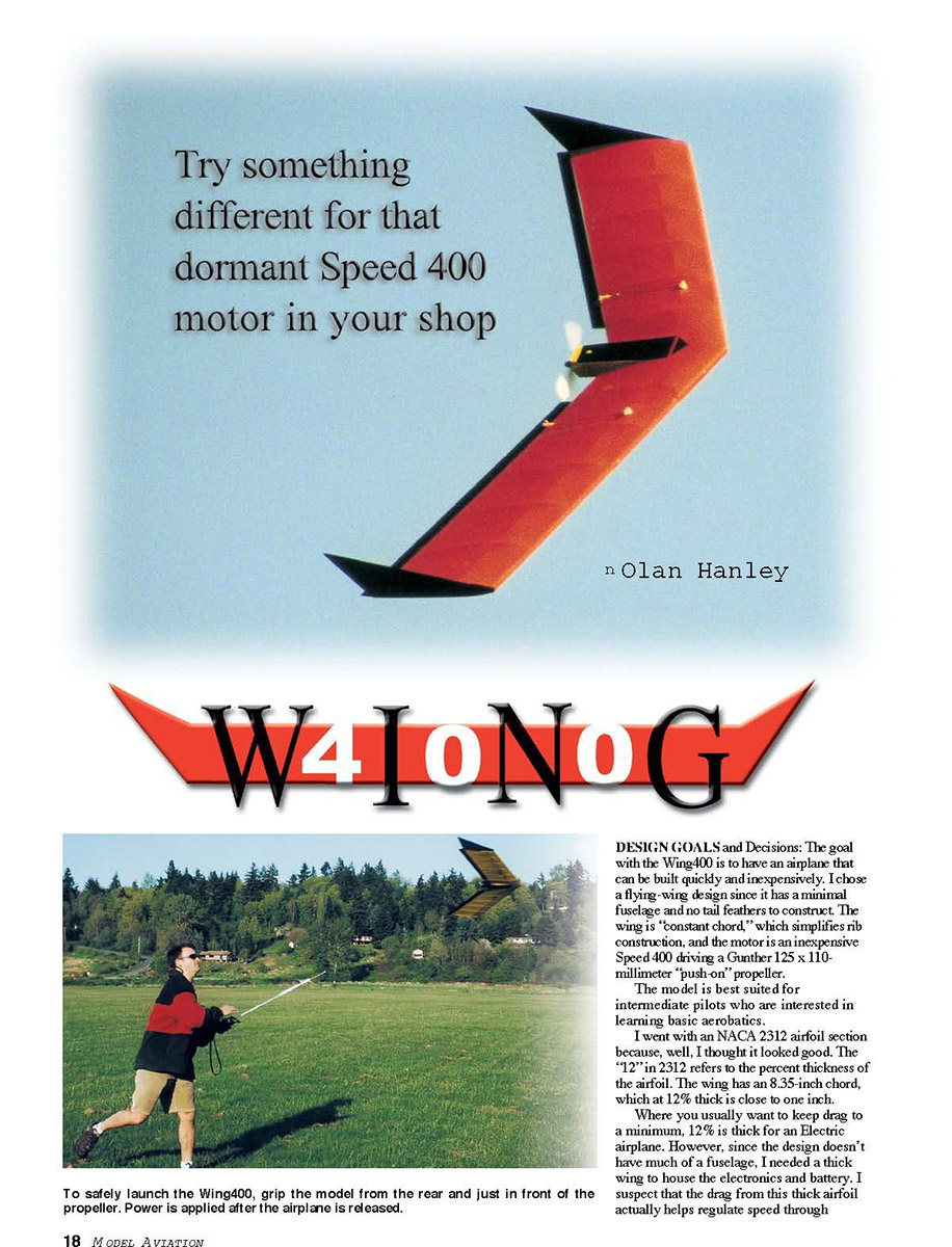
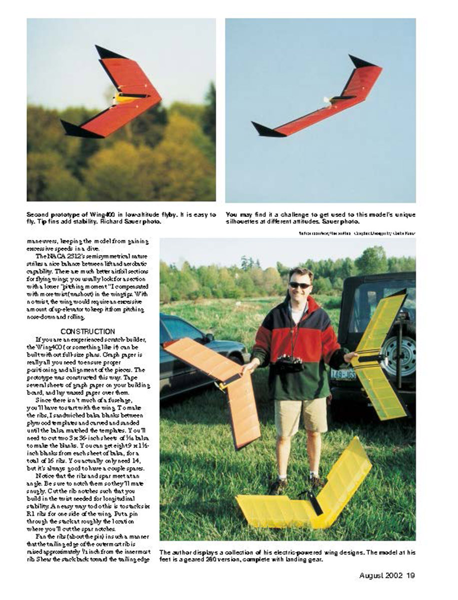

Wing400
Nolan Hanley
DESIGN GOALS and Decisions: The goal with the Wing400 is to have an airplane that can be built quickly and inexpensively. I chose a flying-wing design since it has a minimal fuselage and no tail feathers to construct. The wing is "constant chord," which simplifies rib construction, and the motor is an inexpensive Speed 400 driving a Gurney 125 x 110-millimeter "push-on" propeller.
The model is best suited for intermediate pilots who are interested in learning basic aerobatics.
I went with an NACA 2312 airfoil section because, well, I thought it looked good. The "12" in 2312 refers to the percent thickness of the airfoil. The wing has an 8.35-inch chord, which at 12% thick is close to one inch.
Where you usually want to keep drag to a minimum, 12% is thick for an electric airplane. However, since the design doesn't have much of a fuselage, I needed a thick wing to house the electronics and battery. I suspect that the drag from this thick airfoil actually helps regulate speed through maneuvers, keeping the model from gaining excessive speed in a dive.
The NACA 2312's semisymmetrical nature strikes a nice balance between lift and aerobatic capability. There are much better airfoil sections for flying wings; you usually look for a section with a lower "pitch-in moment" (less nose-down with more twist/torsion) in the wing tips. With no twist, the wing would require an excessive amount of up elevator to keep it from pitching nose-down and rolling.
CONSTRUCTION
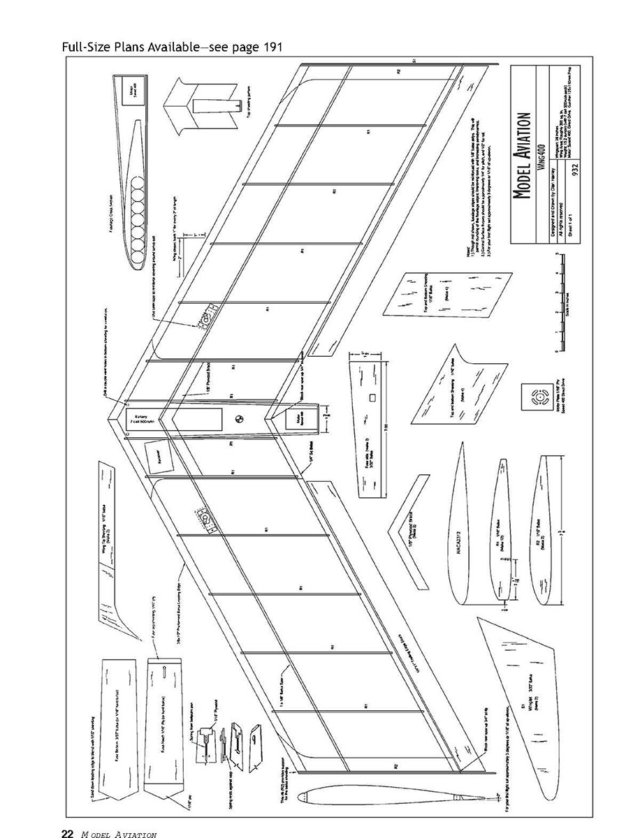
If you are an experienced scratch builder, the Wing400 (or something like it) can be built without full-size plans. Graph paper is really all you need to ensure proper positioning and alignment of the pieces. The prototype was constructed this way. Tape several sheets of graph paper on your building board, and lay waxed paper over them.
Since there isn't much of a fuselage, you'll have to start with the wing. To make the ribs, I sandwiched balsa blanks between plywood templates and carved and sanded until the blank matched the template. You'll need two 3-5/8-inch sheets of 1/16 balsa to make the blanks. You can get eight 9 x 11-1/2-inch blanks from each sheet of balsa, for a total of 16 ribs. You actually only need 14, but it's always good to have a couple spares.
Note the rib and spar meet at an angle. Be sure to notch them so they'll mate snugly. Cut the rib notches such that you build in the twist needed for longitudinal stability. A neat way to do this is to tack one rib for one side of the wing. Put a pin through the spar at roughly the location where you're to cut the spar notches.
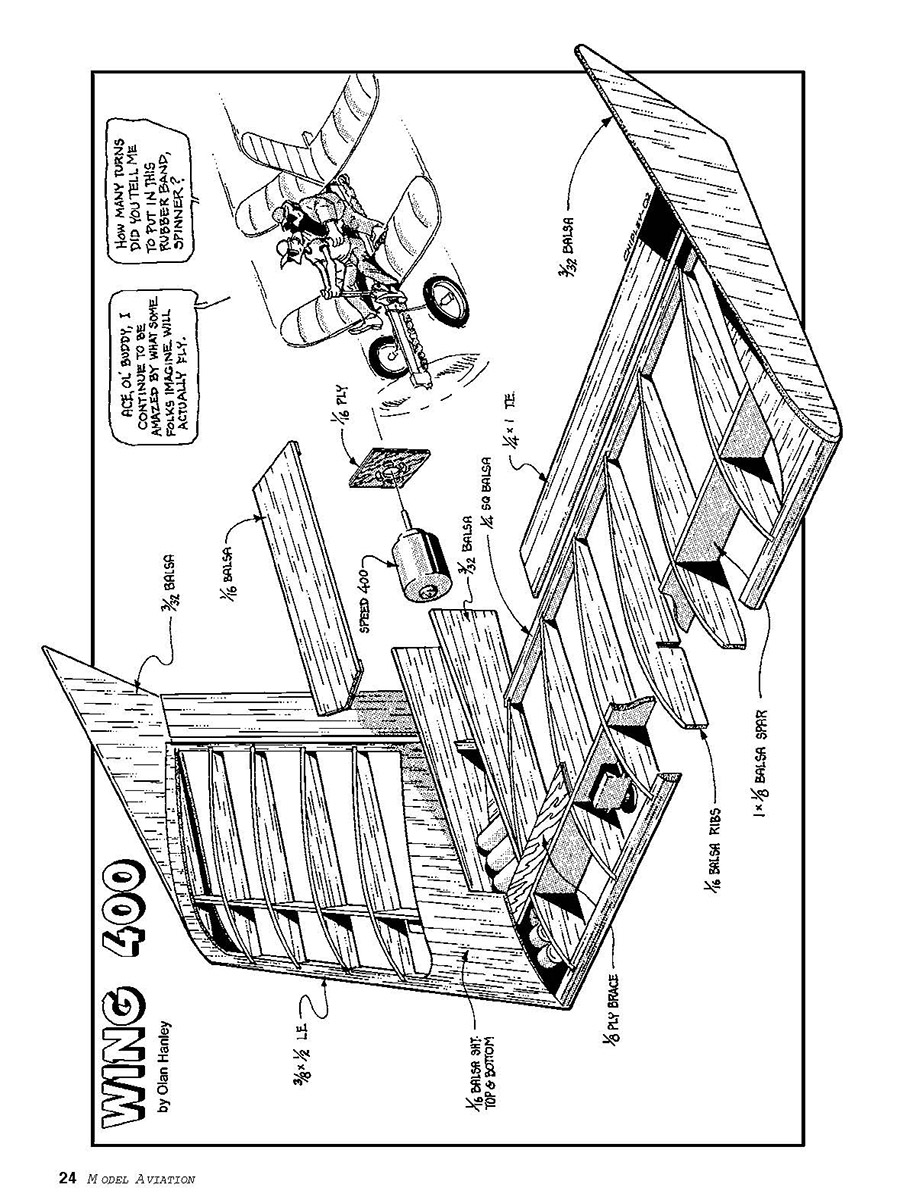
Fan the ribs (about the pin) in such a manner that the trailing edge of the outermost rib is raised approximately 1/16 inch from the innermost rib. Show the notch back toward the trailing edge so that the angle formed roughly follows the sweep of the wing. That may have been complicated to follow; look closely at the accompanying photo. With the wing ribs stacked in this contorted fashion, we can cut all the notches at once. Since the ribs and the wing spar are one-inch tall, we'll notch each halfway through so that they can be slid together.
If your workspace is cramped, you can build each wing half separately, but I prefer to lay up both at the same time. (It helps ensure that the halves meet properly.) Position the wing spars on the building surface. Don't glue the halves together yet, but you should sand them so that they meet flush at the center. The spars should be swept back at a slope of one inch for every two inches out. The length of each spar half is slightly more than 20 inches, but don't cut them until you have them positioned on the building board. Pin them so that they stand vertical.
Cut and sand the preformed leading-edge halves and the 1/4 square trailing-edge halves so that they meet flush in the middle, and follow the same slope as the spar halves (but don't glue them together yet). Notch them in approximately 3/8 inch where they meet the ribs to ensure a stronger joint. Cut them roughly to length as shown on the plans.
Block the trailing-edge pieces up 1/4 inch where they meet in the center, and block them up 3/4 inch at the wingtips. Carefully slide each rib into position on the spar and apply glue. Glue the leading and trailing edge pieces to the ribs. Sand the spars, leading edges, and trailing edges at the wingtips so that they are even, then attach the two end ribs (R2).
Separate the wing halves enough that you can slide the fuselage sides into position. The 1/4 square trailing edge should pass through the fuselage walls and connect in the center. At the front of the fuselage walls where they meet the wing spar, they are one-inch tall, or the same thickness as the wing.
The walls are a bit taller at the rear where the motor is mounted. This is necessary because the motor needs extra room. If you plan to use a different motor from what I recommend, be sure to adjust the fuselage height at the rear to accommodate it.
The fuselage walls are glued to the wing spar at the front and against the innermost ribs. They are allowed to taper slightly toward one another, away from the ribs, at the rear, as shown on the plans. The walls should rest flat on your building board and hold up the trailing edge of the wing approximately 1/4 inch.
You're ready to glue the wing halves together. It's probably best to use a less-brittle adhesive such as epoxy, but thick cyanoacrylate glue (CyA) will work. After the glue dries, cut new notches into the spars and ribs and test-fit the fuselage walls. When everything fits, glass the center joint on the bottom with 1/2-oz fiberglass cloth and epoxy.
Rib Generation for a Constant-Chord Wing
1) Tack-glue the airfoil drawing or computer printout on 1/16 plywood.
2) Use a scroll saw to cut out the airfoil template. Cut slightly wide, then sand to shape. Make two 1/16 plywood templates.
3) Stack the templates, drill two holes (one at each end), and bolt them together. Carefully sand them so that they are identical.
4) Roughly cut 1/16 sheets of balsa to make rib "blanks." I typically divide a 3 x 36-inch sheet of balsa into equal rectangular shapes that are slightly larger than my rib templates. Don't try to squeeze too many onto a single sheet. It's safer to make each blank a little larger than needed. Be sure to cut a few more rib blanks than you think you'll need. I always seem to damage one or two ribs when I'm constructing a wing.
5) Stack the balsa blanks, and center one of the plywood templates on the top of the stack.
6) Using the holes you drilled in the template as a guide, drill completely through all the balsa blanks. Try to drill straight down. A drill press helps, but you can do it with a handheld drill.
7) Sandwich the balsa ribs between both templates, and bolt them together.
8) Carefully carve then sand the balsa blanks to match the plywood templates.
Cut two 1/8-inch plywood braces to fit between the two innermost ribs and fuselage sides to accommodate the 1/8-inch plywood braces. The braces should rest firmly against the spar—one on top of the wing, and one on the bottom. Epoxy the braces into position. You can also epoxy the 1/16 plywood motor mount into position between the fuselage walls at the rear.
Once everything is dry, cut an opening in the wing spar between the plywood braces to accommodate the battery. The battery will need to rest almost all the way up against the leading edge of the wing for balance.
Glue small triangle (or square) sticks into the edges of the fuselage where the walls will meet the floor and the ceiling. This will let you round off the edges of the fuselage for a less boxy look.
Apply the top wing sheeting as shown on the plans. The templates for these pieces are intentionally a bit larger than needed, to give flexibility in placement. Trim and sand off any excess sheeting that hangs off the front or back ends.
Cut the fuselage hatch, and use whatever mechanism you like to keep it shut. A screw is the simplest, but I like to make a little sliding latch using 1/16 plywood and a spring from an old ballpoint pen. Do not apply the bottom sheeting just yet.
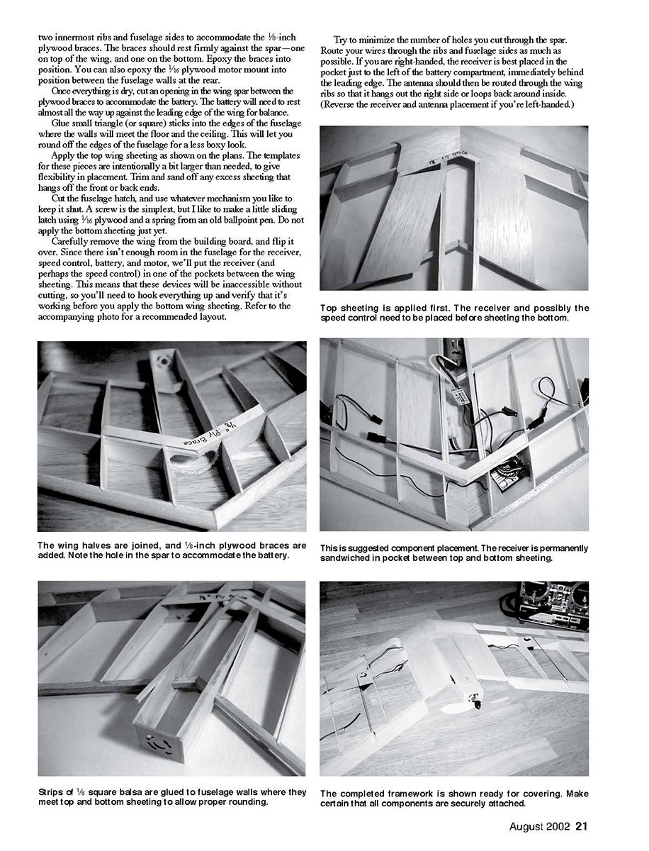
Carefully remove the wing from the building board, and flip it over. Since there isn't enough room in the fuselage for the receiver, speed control, battery, and motor, we'll put the receiver (and perhaps the speed control) in one of the pockets between the wing sheeting. This means that these devices will be inaccessible without cutting, so you'll need to hook everything up and verify that it's working before you apply the bottom wing sheeting. Refer to the accompanying photo for a recommended layout.
Try to minimize the number of holes you cut through the spar. Route your wires through the ribs and fuselage sides as much as possible. If you are right-handed, the receiver is best placed in the pocket just to the left of the battery compartment, immediately behind the leading edge. The antenna should then be routed through the wing ribs so that it hangs out the right side or loops back around inside. (Reverse the receiver and antenna placement if you're left-handed.)
I'm told that looping the antenna back around inside the wing can hurt the range. I haven't noticed any problems, but be sure to perform a radio range check regardless! The speed control is best placed last such that it balances the airplane from left to right. In general, try to place items as far forward as possible to help offset the motor's weight. (The battery can't quite do it alone, and you don't want to be forced to add lead.)
The servos should be mounted so that they protrude from the top of the wing. The model will be landing on its belly, so we can't have them coming out on the bottom. Secure the servos directly to the spar with epoxy or sticky servo tape. Avoid the grommets and screws; they add weight. The servos are intentionally mounted rather far forward to help balance the airplane.
It's time to apply the bottom sheeting and wingtips. It's imperative that you double-check your electrical hookup before sealing the receiver into the wing. Make sure that the servo and speed-control connectors are pushed snugly into the receiver. Verify that the servos move in the desired direction.
Once you're confident of the electronics, apply the bottom sheeting starting with the 3/32-inch fuselage bottom. Since the fuselage bottom is thicker than the surrounding 1/16 sheeting, sand down the leading edge slightly to avoid an abrupt seam. Apply the sheeting in a pattern similar to the top of the wing.
Glue the wingtips on last, after all bottom sheeting is in place.
Cut elevons to length from 1 x 1/4-inch trailing-edge stock. Bevel the front of the elevons so that they can rock freely up and down about a hinge point. Cut control horns from 1/16 plywood, or purchase small, commercial, plastic control horns. Position the control horns in-line with the servo arms. Use .039-inch-diameter, or heavier, piano wire for pushrods.
Use Z-bends on the servo arms and ball-joint connectors on the elevon control horns. (Ball-joint connectors are essential to allow free movement of the control surfaces.) Since we use relatively little control throw, it's imperative that connections be snug and nearly free of play.
Round the fuselage edges, and lightly sand the rest of the airplane to prepare for covering and finish.
W410NG Type: RC Electric flying wing Wingspan: 36 inches Motor: Six-volt Speed 400 with seven-cell 500 mAh battery pack Flying weight: 14-16 ounces with battery Construction: Balsa and plywood Covering/finish: MonoKote®
WING 400
by Nolan Hanley
downward position). Roll control is more forgiving. You can probably tolerate as much as 3/8 inch either way.
You'll probably need to use the shortest possible servo arms and rather long (approximately 8-inch) control-surface horn. If you have a programmable radio with Adjustable Travel Volume, you can reduce the size of the control surface throws and use your radio to limit the control throws.
Flying: Be sure to perform a radio check before launching. I get the most interference at lower motor speeds, so I usually perform my tests with the motor running at slightly less than half throttle. For me, the biggest contributor to radio interference has been my choice of speed control. I've been happy with Jeti, Great Planes, and New Creation R/C speed controllers.
If you detect any interference, make sure you've used the recommended suppression capacitors. At the very least you should have a .47 microfarad (uF) capacitor across the motor terminals. Great Planes provides a couple .10 uF capacitors from each terminal to the motor case. If you still have problems, you can try hanging the antenna outside the wing, but my advice is to try a different brand of speed control (perhaps one that operates at a different switching frequency).
Hand-launching the Wing400 is a challenge. You have to launch it with the motor stopped; otherwise, your fingers will pass through a spinning propeller, causing who knows how much damage. I spin the fuselage just in front of the propeller, give it a gentle heave, then apply full throttle. For your first flight, you could have an assistant; someone needs to hunch the airplane, and someone needs to have both hands on the transmitter.
The recommended control-trim setting is aggressive; be careful not to overtrim the airplane until you get it trimmed out. I strongly recommend launching over soft ground. Tall grass is best. Once the model is trimmed, it's pretty easy to launch. A firm toe is really all it requires.
I confess that my first flights were less than flawless. I launched the airplane at least a dozen times before it stayed in the air. It's a tough model, but I'm amazed that it survived. All my problems were attributed to the model being tail-heavy and having way too much control throw.
I started out trying to use a lightweight 350 mAh pack that wasn't heavy enough to balance the airplane. Once I stuck a much larger 500 mAh pack in the model and reduced the control throws, it flew beautifully. After a bit of trim adjustment, I had it doing loops and rolls. The airplane isn't difficult to trim; if you follow my recommendations under "Control Throws," you'll be close. I've built a second Wing400 that flies perfectly on the first toss.
The airplane has plenty of power to spare, yet isn't overly fast. It turns out to be an excellent aerobatics trainer. It's easy to perform inside and outside loops and a variety of rolls. The model seems to have a rather narrow speed range, and it doesn't get out of control easily. The large twist or washout in the wingtips, combined with a constant-chord wing, normally results in forgiving stalls.
However, if you pull back hard on the stick and hold a tight loop, one wing will stall before the other. If it's too severe, try wrapping a little more washout into the stalling side.
If the airplane seems excessively sluggish on launch and tends to stall, it's probably tail-heavy. Double-check the balance point. If it seems okay, try reducing the amount of up-elevator. If you have a hard time keeping the nose up during landing, try shifting the weight (with the battery pack) back a bit.
With a Graupner 6-volt Speed 400 motor, a Gunter propeller, and a seven-cell 600 mAh A/E pack, useful motor run at full throttle is approximately four minutes. (The Great Planes speed controller shuts the motor off after roughly 5 1/2 minutes.) I fly the model at approximately full throttle. From launch to landing, flights are somewhere between seven to eight minutes, and that's with nearly constant aerobatics.
The Wing400 is a blast to fly. If you build one, please let me know how it turns out. I can be reached by E-mail at [email protected]. I will be only too happy to answer questions, and I would love to hear your suggestions for improvements.
Sources:
Wing area: 300 square inches Wing loading: eight ounces/square foot Control functions: three-channel, throttle, and elevons (requires elevon or V-tail mixing)
Sources:
Additional information about flying wings:
There are some excellent Web sites with more about flying wings. Check out http://beadec1.ea.bs.dlr.de/Airfoils/flywing1.htm and http://amber.aae.uiuc.edu/~mselig/flyingWingAfs/.
Computer airfoil generators:
There are several free airfoil-generating programs available on the Internet. I highly recommend the following.
1) Airfoil, Michele Boland (Boland Aeroplane Works): Generates Quabeck, NACA 4 and 5 series, and custom airfoils (from files). Requires a personal computer running Windows®. http://rampages.onramp.net/~micheleb
2) Autofoil, Steven Brooke (Moke Electronics): Plots NACA four-digit and custom airfoils. Can generate DXF files for CAD (computer-aided design) use. Requires a personal computer running Windows®.
3) Plotfoil, Shamin Mohamed: This is a package of utilities for airfoil generation. It's a bit more difficult to use than either of the preceding programs but is probably the most powerful. If you are running Windows®, be sure to pick up Michael Shellim's PfWin front-end, which makes plotfoil easier to use. Plotfoil is available for DOS or Unix. www.drones.com/rec.models.rc.air
Transcribed from original scans by AI. Minor OCR errors may remain.

