
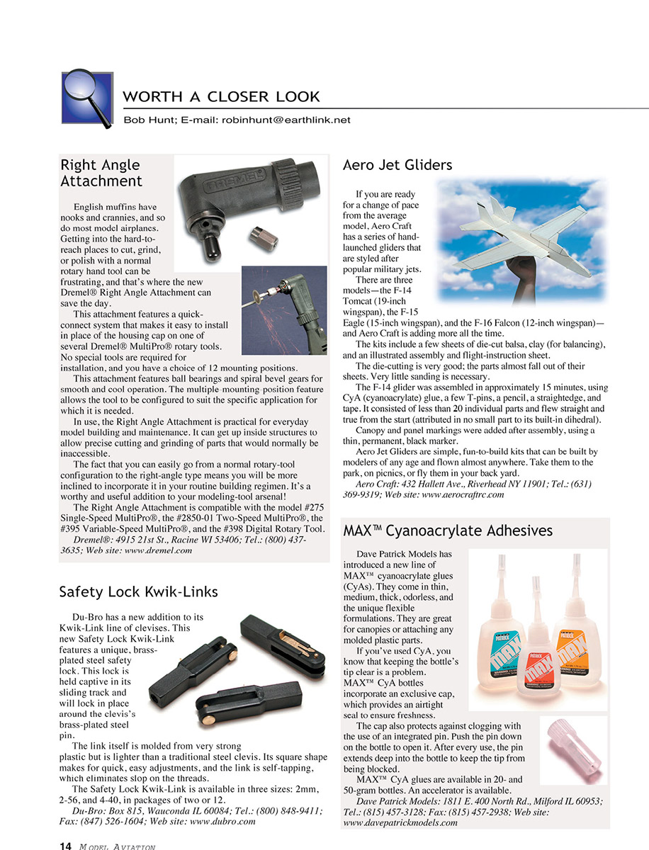
WORTH A CLOSER LOOK
Bob Hunt; E-mail: [email protected]
Right Angle Attachment
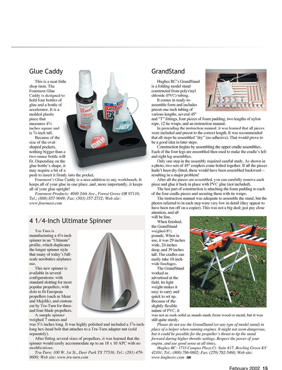
English muffins have nooks and crannies, and so do most model airplanes. Getting into the hard-to-reach places to cut, grind, or polish with a normal rotary hand tool can be frustrating, and that's where the new Dremel® Right Angle Attachment can save the day.
This attachment features a quick-connect system that makes it easy to install in place of the housing cap on one of several Dremel® MultiPro® rotary tools. No special tools are required for installation, and you have a choice of 12 mounting positions.
This attachment features ball bearings and spiral bevel gears for smooth and cool operation. The multiple-mounting-position feature allows the tool to be configured to suit the specific application for which it is needed.
In use, the Right Angle Attachment is practical for everyday model building and maintenance. It can get up inside structures to allow precise cutting and grinding of parts that would normally be inaccessible.
The fact that you can easily go from a normal rotary-tool configuration to the right-angle type means you will be more inclined to incorporate it in your routine building regimen. It's a worthy and useful addition to your modeling-tool arsenal!
The Right Angle Attachment is compatible with model #275 Single-Speed MultiPro®, the #2850-01 Two-Speed MultiPro®, the #395 Variable-Speed MultiPro®, and the #398 Digital Rotary Tool.
Dremel®; 4915 21st St., Racine WI 53406; Tel.: (800) 437-3635; Web site: www.dremel.com
Safety Lock Kwik-Links
Du-Bro has a new addition to its Kwik-Link line of clevises. This new Safety Lock Kwik-Link features a unique, brass-plated steel safety lock. This lock is held captive in its sliding track and will lock in place around the clevis's brass-plated steel pin.
The link itself is molded from very strong plastic but is lighter than a traditional steel clevis. Its square shape makes for quick, easy adjustments, and the link is self-tapping, which eliminates slop on the threads.
The Safety Lock Kwik-Link is available in three sizes: 2mm, 2.5mm, and 4-40, in packages of two or 12.
Du-Bro; Box 815, Wauconda IL 60084; Tel.: (800) 848-9411; Fax: (847) 526-1604; Web site: www.dubro.com
Aero Jet Gliders
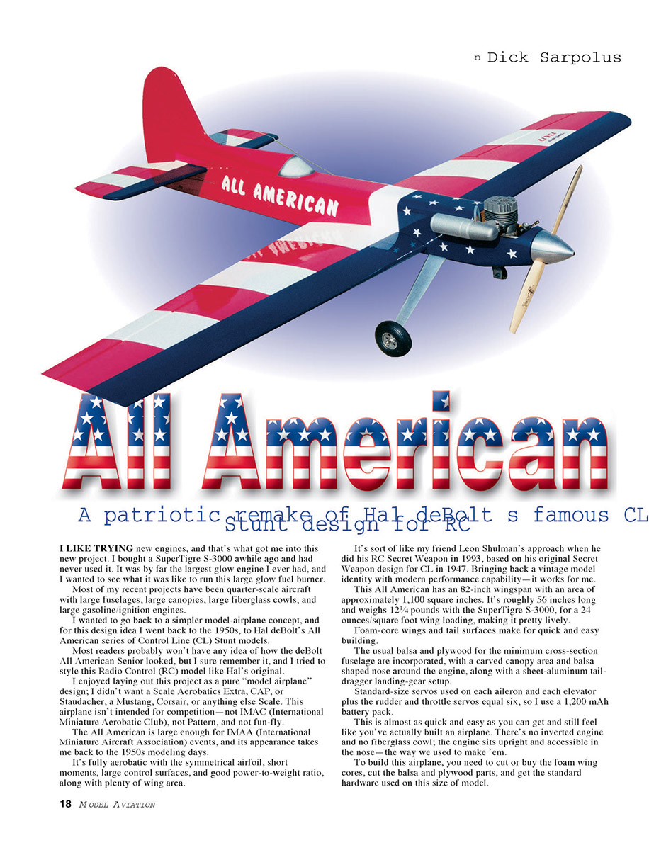
If you are ready for a change of pace from the average model, Aero Craft has a series of hand-launched gliders that are styled after popular military jets.
There are three models—the F-14 Tomcat (19-inch wingspan), the F-15 Eagle (15-inch wingspan), and the F-16 Falcon (12-inch wingspan)—and Aero Craft is adding more all the time.
The kits include a few sheets of die-cut balsa, clay (for balancing), and an illustrated assembly and flight-instruction sheet.
The die-cutting is very good; the parts almost fall out of their sheets. Very little sanding is necessary.
The F-14 glider was assembled in approximately 15 minutes, using CyA (cyanoacrylate) glue, a few T-pins, a pencil, a straightedge, and tape. It consisted of less than 20 individual parts and flew straight and true from the start (attributed in no small part to its built-in dihedral).
Canopy and panel markings were added after assembly, using a thin, permanent, black marker.
Aero Jet Gliders are simple, fun-to-build kits that can be built by modelers of any age and flown almost anywhere. Take them to the park, on picnics, or fly them in your back yard.
Aero Craft; 432 Hallett Ave., Riverhead NY 11901; Tel.: (631) 369-9319; Web site: www.aerocraftrc.com
MAX™ Cyanoacrylate Adhesives
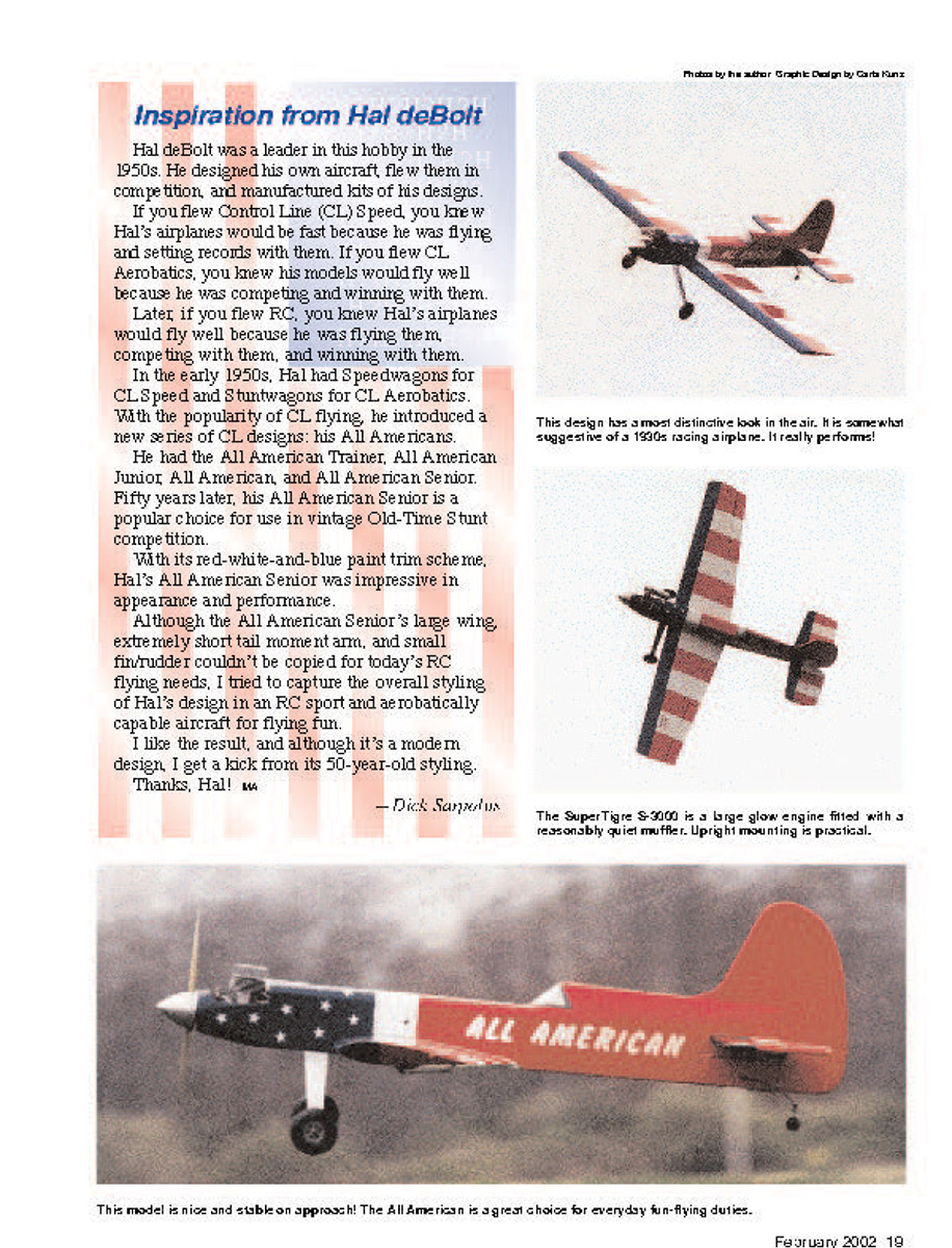
Dave Patrick Models has introduced a new line of MAX™ cyanoacrylate glues (CyAs). They come in thin, medium, thick, odorless, and the unique flexible formulations. They are great for canopies or attaching any molded plastic parts.
If you've used CyA, you know that keeping the bottle's tip clear is a problem. MAX™ CyA bottles incorporate an exclusive cap, which provides an airtight seal to ensure freshness.
The cap also protects against clogging with the use of an integrated pin. Push the pin down on the bottle to open it. After every use, the pin extends deep into the bottle to keep the tip from being blocked.
MAX™ CyA glues are available in 20- and 50-gram bottles. An accelerator is available.
Dave Patrick Models; 1811 E. 400 North Rd., Milford IL 60953; Tel.: (815) 457-3128; Fax: (815) 457-2938; Web site: www.davepatrickmodels.com
Glue Caddy
This is a neat little shop item. Fourmost Glue Caddy is designed to hold four bottles of glue and a bottle of accelerator. It is a molded plastic piece that measures 4¼ inches square and is 3¼-inch tall.
Because of the size of the oval-shaped pockets, nothing bigger than a two-ounce bottle will fit. Depending on the glue bottle's shape, it may require a bit of a push to insert it firmly into the pocket.
Fourmost's Glue Caddy is a nice addition to any workbench. It keeps all of your glue in one place, and, more importantly, it keeps all of your glue upright!
Fourmost Products; 4040 24th Ave., Forest Grove OR 97116; Tel.: (888) 857-9049; Fax: (503) 357-2732; Web site: www.fourmost.com
4 1/4-Inch Ultimate Spinner
Tru-Turn is manufacturing a 4¼-inch spinner in an "Ultimate" profile, which duplicates the longer spinner style that many of today's full-scale aerobatics airplanes use.
This new spinner is available in several configurations: with standard slotting for most popular propellers, with slots to fit European propellers (such as Menz and Mejzlik), and custom-cut by Tru-Turn for three- and four-blade propellers.
A sample spinner weighed 7 ounces and was 5¼ inches long. It was highly polished and included a 3⅞-inch-long hex-head bolt that attaches to a Tru-Turn adapter nut (sold separately).
After fitting several sizes of propellers, it was learned that the spinner would easily accommodate up to an 18 x 10 APC with no modifications.
Tru-Turn; 100 W. 1st St., Deer Park TX 77536; Tel.: (281) 479-9600; Web site: www.tru-turn.com
GrandStand
Hughes RC's GrandStand is a folding model stand constructed from polyvinyl chloride (PVC) tubing.
It comes in ready-to-assemble form and includes precut one-inch tubing of various lengths, several 45° and "T" fittings, four pieces of foam padding, two lengths of nylon rope, 12 tie wraps, and an instruction manual.
In preceding the instruction manual, it was learned that all pieces were included and precut to the correct length. It was recommended that all steps be assembled "dry" (no adhesive). That would prove to be a good idea in later steps.
Construction begins by assembling the upper cradle assemblies. Each of the four legs are assembled then used to make the cradle's left and right leg assemblies.
Only one step in the assembly required careful study. As shown in a photo, two sets of 45° couplers come bolted together. If all the pieces hadn't been dry-fitted, these would have been assembled backward—resulting in a major problem!
After all the pieces are assembled, you can carefully remove each piece and glue it back in place with PVC glue (not included).
The last part of construction is attaching the foam padding to each of the four cradle pieces and securing them with tie wraps.
If the instruction manual was adequate to assemble the stand, the photos referred to in each step were very low in detail (they appear to have been run off on a copier). This was not a big deal; just pay close attention, and all will be fine.
When finished, the GrandStand weighed 8½ pounds. When in use, it was 29 inches wide, 24 inches deep, and 39 inches tall. The cradles can easily take 10-inch-wide fuselages.
The GrandStand worked as advertised at the field. Its light weight makes it easy to carry and quick to set up. Because of the slightly flexible nature of PVC, it was not as rock-solid as stands made from wood or metal, but it was still quite sturdy.
Please do not use the GrandStand (or any type of model stand) in place of a helper when running engines. It might not seem dangerous, but it could be possible for the propeller's thrust to tip the stand forward during higher throttle settings. Respect the power of your engine, and use good sense at all times.
Hughes RC; 1733 Campus Plaza Ct. Suite #17, Bowling Green KY 42101; Tel.: (800) 786-0802; Fax: (270) 782-5468; Web site: www.hughesrc.com
All American
A patriotic remake of Hal deBolt's famous CL stunt design for RC
I LIKE TRYING new engines, and that's what got me into this new project. I bought a SuperTiger S-3000 awhile ago and had never used it. It was by far the largest glow engine I ever had, and I wanted to see what it was like to run this large glow fuel burner.
Most of my recent projects have been quarter-scale aircraft with large fuselages, large canopies, large fiberglass cowls, and large gasoline/ignition engines.
I wanted to go back to a simpler model-airplane concept, and for this design idea I went back to the 1950s, to Hal deBolt's All American series of Control Line (CL) Stunt models.
Most readers probably won't have any idea of how the deBolt All American Senior looked, but I sure remember it, and I tried to style this Radio Control (RC) model like Hal's original.
I enjoyed laying out this project as a pure model airplane design; I didn't want a Scale Aerobatics Extra, CAP, or Staudacher, a Mustang, Corsair, or anything else Scale. This airplane isn't intended for competition — not IMAC (International Miniature Aerobatic Club), not Pattern, and not fun-fly.
The All American is large enough for IMAA (International Miniature Aircraft Association) events, and its appearance takes me back to the 1950s modeling days.
It's fully aerobatic with the symmetrical airfoil, short moments, large control surfaces, and good power-to-weight ratio, along with plenty of wing area.
It's sort of like my friend Leon Shulman's approach when he did his RC Secret Weapon in 1993, based on his original Secret Weapon design for CL in 1947. Bringing back a vintage model identity with modern performance capability — it works for me.
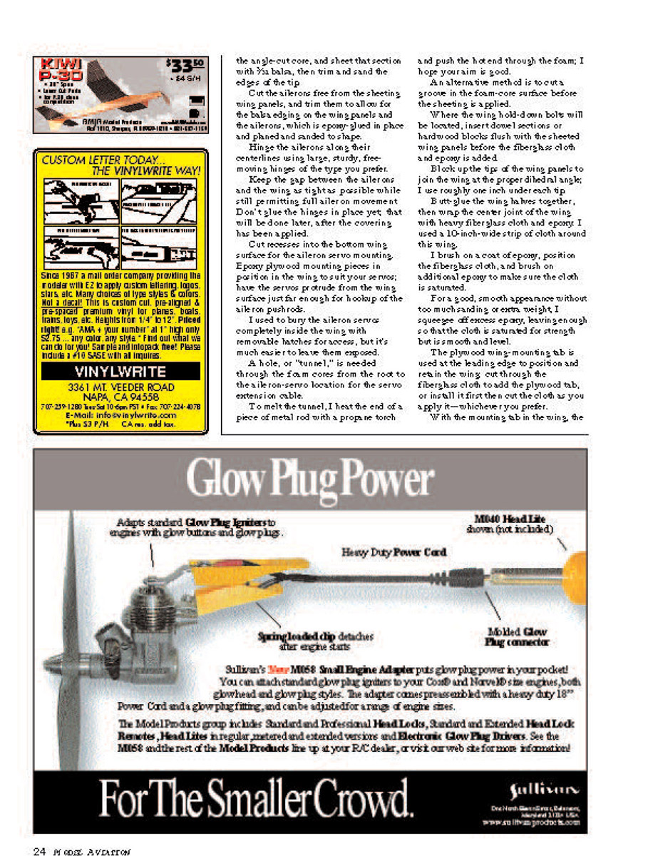
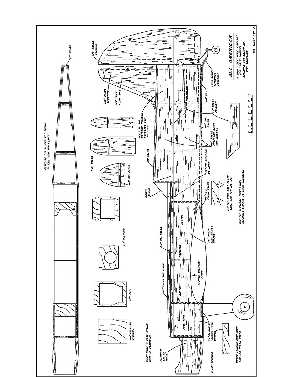
This All American has an 82-inch wingspan with an area of approximately 1,100 square inches. It's roughly 56 inches long and weighs 12½ pounds with the SuperTiger S-3000 for a 24 ounces/sq. ft. wing loading, making it pretty lively.
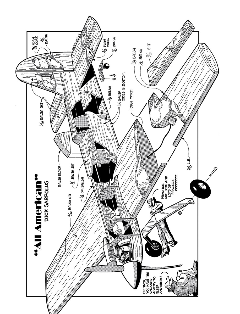
Foam-core wings and tail surfaces make for quick and easy building.
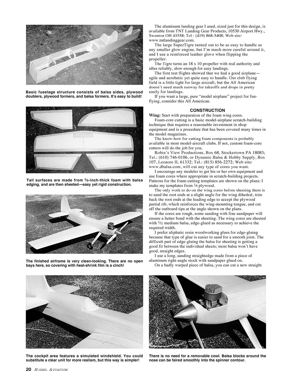
The usual balsa and plywood for the minimum cross-section fuselage are incorporated, with a carved canopy area and balsa-shaped nose around the engine, along with a sheet-aluminum tail-dragger landing-gear setup.
Standard-size servos used on each aileron and each elevator plus the rudder and throttle servos equal six, so I use a 1,200 mAh battery pack.
This is almost as quick and easy as you can get and still feel like you've actually built an airplane. There's no inverted engine and no fiberglass cowl; the engine sits upright and accessible in the nose — the way we used to make 'em.
To build this airplane, you need to cut or buy the foam wing cores, cut the balsa and plywood parts, and get the standard hardware used on this size of model.
Inspiration from Hal deBolt
Hal deBolt was a leader in this hobby in the 1950s. He designed his own aircraft, flew them in competition, and manufactured kits of his designs.
If you flew Control Line (CL) Speed you knew Hal's airplanes would be fast because he was flying and setting records with them. If you flew CL Aerobatics, you knew his models would fly well because he was competing and winning with them.
Later, if you flew RC, you knew Hal's airplanes would fly well because he was flying them, competing with them, and winning with them.
In the early 1950s, Hal had Speedwagons for CL Speed and Stuntwagons for CL Aerobatics. With the popularity of CL flying, he introduced a new series of CL designs: his All Americans.
He had the All American Trainer, All American Junior, All American, and All American Senior. Fifty years later, his All American Senior is a popular choice for use in vintage Old-Time Stunt competition.
With its red-white-and-blue paint trim scheme, Hal's All American Senior was impressive in appearance and performance.
Although the All American Senior's large wing, extremely short tail moment arm, and small fin/rudder couldn't be copied for today's RC flying needs, I tried to capture the overall styling of Hal's design in an RC sport and aerobatically capable aircraft for flying fun.
I like the result, and although it's a modern design, I get a kick from its 50-year-old styling.
Thanks, Hal! — Dick Sampson
The aluminum landing gear I used, sized just for this design, is available from TNT Landing Gear Products, 10530 Airport Hwy., Swanton OH 43558; Tel.: (419) 868-5408; Web site: www.tntlandinggear.com.
The large SuperTigre turned out to be as easy to handle as any smaller glow engine, but I'm much more careful around it, and I use a reinforced leather glove when flipping the propeller.
The Tigre turns an 18 x 10 propeller with real authority and idles reliably, slow enough for easy landings.
The first test flights showed that we had a good airplane—agile and aerobatic yet quite easy to handle. Our club flying field is a little tight for large aircraft, but the All American doesn't need much runway for takeoffs and drops in pretty easily for landings.
If you want a large, pure "model airplane" project for fun-flying, consider this All American.
CONSTRUCTION
Wing: Start with preparation of the foam wing cores.
Foam-core cutting is a basic model-airplane scratch-building technique that requires a reasonable investment in shop equipment and is a procedure that has been covered many times in the model magazines.
The know-how for cutting foam components is probably available in most model-aircraft clubs. If not, custom foam-core cutters will do the job for you.
Robin's View Productions, Box 68, Stockertown PA 18083; Tel.: (610) 746-0106, or Dynamic Balsa & Hobby Supply, Box 107, Leonore IL 61332; Tel.: (815) 856-2272; Web site: www.dbalsa.com, will cut any type of cores you want.
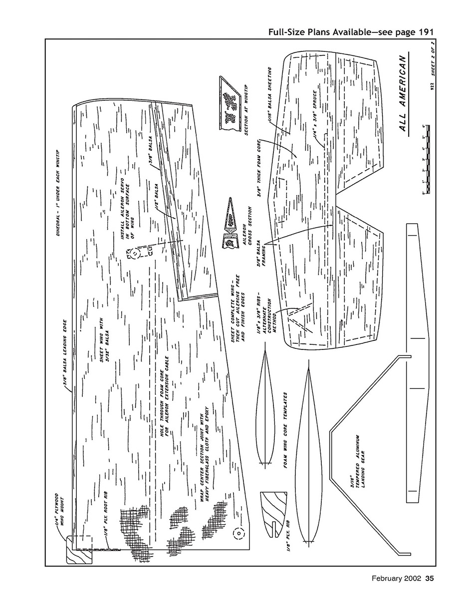
I encourage any modeler to get his or her own equipment and use foam cores where appropriate in scratch-building projects. Patterns for the foam-cutting templates are shown on the plans; I make my templates from 1/8 plywood.
The only work to do on the wing cores before sheeting them is to sand the root ends at a slight angle for the wing dihedral, trim back the root ends at the leading edge to accept the plywood partial rib, which reinforces the wing-mounting tongue, and cut off the outboard tips at the angle shown on the plans.
If the cores are rough, some sanding with fine sandpaper will ensure a better bond with the sheeting. The wing cores are sheeted with 3/32 medium balsa, edge-glued as necessary to achieve the required width.
I prefer aliphatic resin woodworking glues for edge-gluing because that type of glue is easier to sand for a smooth joint. The difficult part of edge-gluing the balsa for sheeting is getting a good fit between the individual sheets; most balsa won't have good, straight edges.
I use a long, sanding straightedge made from a piece of aluminum right-angle stock with sandpaper glued on.
On a badly warped piece of balsa, you can cut a new straight edge by ripping it on the table saw.
The angle-cut core, and sheet that section with 3/32 balsa, then trim and sand the edges of the tip.
Cut the ailerons free from the sheeting wing panels, and trim them to allow for the balsa edging on the wing panels and the ailerons, which is epoxy-glued in place and planed and sanded to shape.
Hinge the ailerons along their rearlines using large, sturdy, free-moving hinges of the type you prefer. Keep the gap between the aileron and the wing as tight as possible while still permitting full aileron movement. Don't glue the hinges in place yet; that will be done later, after the covering has been applied.
Cut recesses into the bottom wing surface for the aileron servo mounting. Epoxy plywood mounting pieces in position in the wing to suit your servo; have the servo protrude from the wing surface just far enough for hookup of the aileron pushrod.
I used to bury the aileron servo completely inside the wing with removable hatches for access, but it's much easier to have them exposed.
A hole, or "tunnel," is needed through the foam cores from the root to the aileron-servo location for the servo extension cable.
To melt the tunnel, I heat the end of a piece of metal rod with a propane torch and push the hot end through the foam; I hope your aim is good.
An alternative method is to cut a groove in the foam-core surface before the sheeting is applied.
Where the wing hold-down bolt will be located, insert dowel sections or hardwood blocks flush with the sheeting wing panels before the fiberglass cloth and epoxy is added.
Block up the tip of the wing panels to join the wing at the proper dihedral. I use roughly one inch under each tip. Butt-glue the wing halves together, then wrap the center joint of the wing with heavy fiberglass cloth and epoxy. I used a 10-inch-wide strip of cloth around the wing.
I brush on a coat of epoxy, position the fiberglass cloth, and brush on additional epoxy to make sure the cloth is saturated.
For a good, smooth appearance without too much sanding or extra weight, I suggest one or two coats of epoxy, leaving enough so that the cloth is saturated for strength but is smooth and level.
The plywood wing mounting tab is used at the leading edge to position and retain the wing. Cut through the plywood and fiberglass cloth to add the plywood tab, or install it first or cut the cloth as you apply it—whichever you prefer.
The contact area of the fuselage bulkhead retaining the wing mount can be trimmed or shimmed as necessary to get the correct wing-to-fuselage fit.
Fuselage: Select firm to hard 1/8 balsa for the sides, edge-gluing and splicing as necessary to get the size required.
Glue the 1/16 plywood doublers, 1/4 plywood landing-gear-block doublers, balsa wing-saddle doublers, and stabilizer saddle doublers to the two fuselage sides.
I make the 3/16-inch-thick firewall from a piece of 1/4 and a piece of 1/16 plywood glued together.
With one fuselage side flat on the workbench, add the firewall and the next three bulkheads, installing them perpendicular to the side. Glue the second side to those bulkheads and the firewall; the sides are parallel from the firewall to the wing trailing-edge position.
Add triangle stock and fiberglass cloth behind the firewall to reinforce its joint with the sides. I also put several small screws in the firewall through the fuselage sides.
Add the 1/4 plywood landing-gear mount and wing bolt plate to the fuselage.
Pull the tail end together and install the rear bulkheads. A piece of 1/16 plywood on the bottom end of the fuselage serves as the base for the leaf-spring tail-wheel assembly.
The forward top section of the fuselage is made from 1/2 square balsa stringers — one on each side — and a 1/2-inch sheet of balsa on top; the top edges can be nicely rounded.
The rear top section of the fuselage is made from 1/8 balsa sides and a 1/4-inch top piece, rounded to shape.
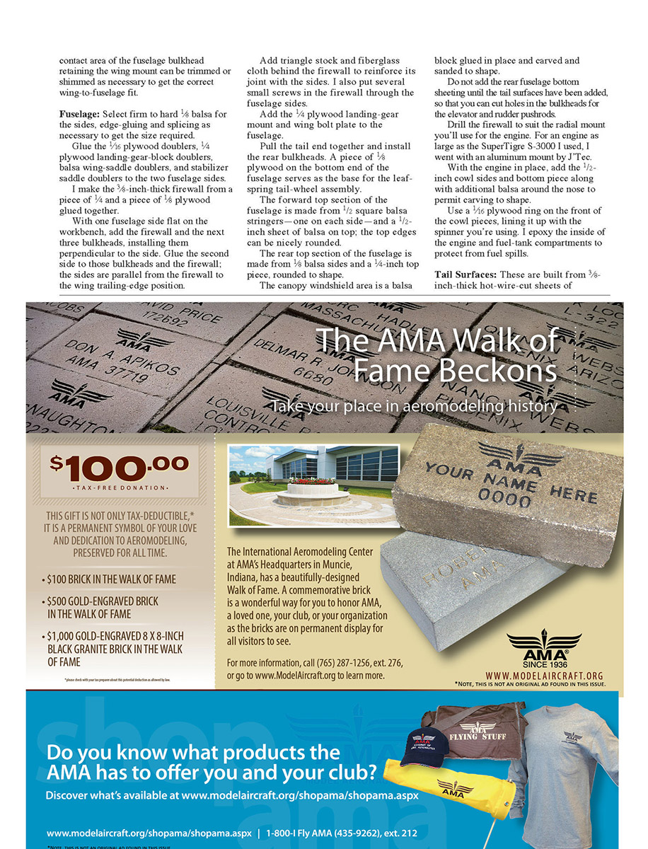
The canopy windshield area is a balsa block glued in place and carved and sanded to shape.
Do not add the rear fuselage bottom sheeting until the tail surfaces have been added, so that you can cut holes in the bulkheads for the elevator and rudder pushrods.
Drill the firewall to suit the radial mount you'll use for the engine. For an engine as large as the SuperTiger S-3000 I used 1.5-inch plywood pieces with an aluminum mount by J-Tec.
With the engine in place, add the 1/2-inch cowl sides and bottom piece along with additional balsa around the nose to permit carving to shape.
Use a 1/16 plywood ring on the front of the cowl pieces, lining it up with the spinner you're using. I epoxy the inside of the engine and fuel-tank compartments to protect from fuel spills.
Tail Surfaces:
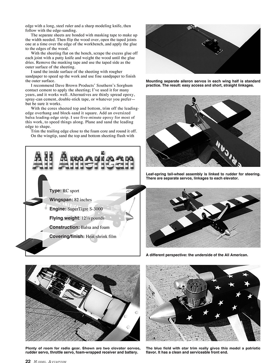
These are built from 3/8-inch-thick hot-wire-cut sheets of Styrofoam® with 3/8 balsa framing added before sheeting the surfaces with 1/16 balsa, just as with the wing foam cores.
Round the leading and trailing edges of the tail surfaces, bevel the elevator and rudder leading edges, and cut the slots or drill the holes along the centerlines of the surfaces for whatever hinge type you're using.
Notch the control surfaces as required to permit a close fit of the surfaces to the main structures, allowing proper movement. Don't glue the hinges in place at this time; you'll do that after covering.
I use 1/4 plywood pads for control-horn mounting, recessing and epoxying the plywood into the elevators and rudder. The heavy-duty nylon horns are mounted with self-tapping screws.
Final Assembly: I mount the wing to the fuselage, adjusting the fit of the wing-mounting tab through the fuselage bulkhead if necessary, and drill and tap the wing mount for the 1/4-20 nylon bolts that hold the wing in place.
With the wing mounted, I add the horizontal stabilizer and align it with the wing. Then I add the vertical fin perpendicular to the stabilizer.
The two elevator pushrods cross inside the fuselage so they can be routed to the servos without interfering with each other. I use ball links on the pushrod ends to provide a positive, slop-free connection to the horns.
Covering: I covered the model with MonoKote® on all surfaces. Before covering, I sanded the model carefully and filled any imperfections with a light filler. I also added the cowl and spinner after covering the fuselage nose area to allow easier finishing.
Landing Gear: The main gear is a leaf-spring type built from 3/32-inch music wire, formed and mounted to the fuselage bottom using blind nuts and 1/8-inch plywood doublers. Wheel pants were added for scale appearance and are mounted to the gear legs with small bolts and straps.
Balance and Control Throws: The model balances at 25% to 30% back from the wing leading edge at the root with full fuel. I set the control throws as follows: elevator ±3/8 inch (dual-rate to ±3/4 inch), rudder ±1-1/4 inch, ailerons ±3/8 inch (dual-rate to ±3/4 inch).
Flying Impressions: The model flies straight and scale-like. Takeoffs are smooth and predictable; landing requires a bit of speed control because of the scale airfoil. The S-3000 provides ample power for sport flying and basic aerobatics. With proper setup, the model is an enjoyable flyable scale replica.
Plans and Parts: The plans include full-size templates for all formers, wing ribs, and tail parts, along with a suggested hardware list and construction notes. If you build to these plans and use the recommended parts, you should end up with a handsome, flyable model that represents the prototype well.
Transcribed from original scans by AI. Minor OCR errors may remain.

