
XB-70 Park Flyer
by Al Clark [email protected]
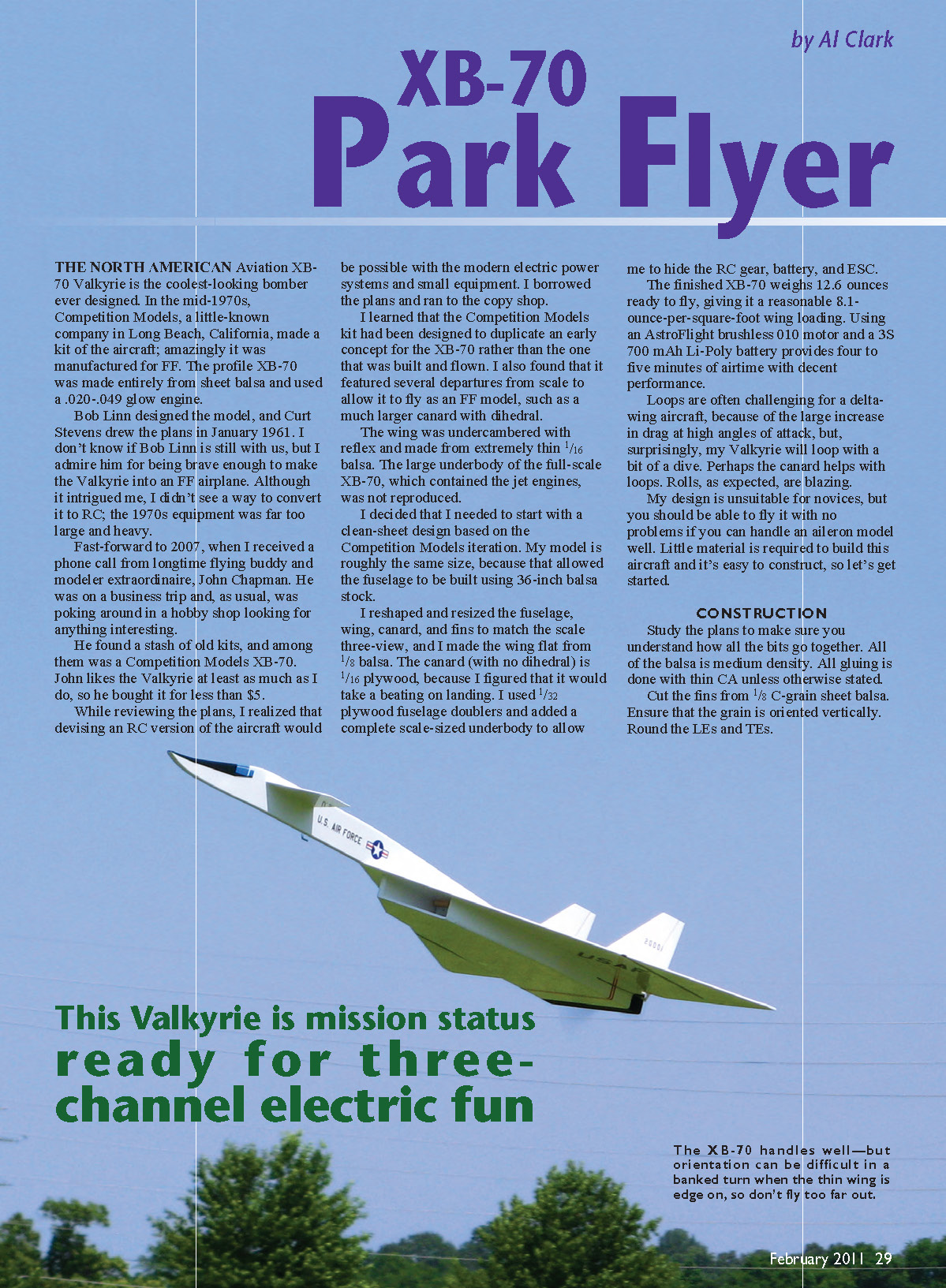
The North American Aviation XB-70 Valkyrie is the coolest-looking bomber ever designed. In the mid-1970s, Competition Models, a little-known company in Long Beach, California, made a kit of the aircraft; amazingly it was manufactured for free-flight (FF). The profile XB-70 was made entirely from sheet balsa and used a .020–.049 glow engine.
Bob Linn designed the model, and Curt Stevens drew the plans in January 1961. Although it intrigued me, I didn't see a way to convert it to RC at the time; 1970s equipment was far too large and heavy.
Fast-forward to 2007, when longtime flying buddy and modeler extraordinaire John Chapman called to say he had found a stash of old kits in a hobby shop — among them a Competition Models XB-70. John bought it for less than $5 and I borrowed the plans.
I learned that the Competition Models kit duplicated an early concept for the XB-70 rather than the one actually built and flown. The kit featured departures from scale to allow it to fly as an FF model, such as a much larger canard with dihedral, an undercambered wing made from extremely thin 1/16 balsa, and no large underbody to reproduce the full-scale jet-engine housings.
I decided to start with a clean-sheet design based on the Competition Models iteration. My model is roughly the same size so the fuselage could be built using 36-inch balsa stock. I reshaped and resized the fuselage, wing, canard, and fins to match the scale three-view, made the wing flat from 1/8 balsa, and built a scale-sized underbody to hide the RC gear, battery, and ESC.
The canard is 1/16 plywood (no dihedral) for strength on landings and to help balance the model. I used 1/32 plywood fuselage doublers and added spruce leading edges on critical parts.
The finished XB-70 weighs 12.6 ounces ready to fly, giving about 8.1 ounces per square foot wing loading. Using an AstroFlight brushless 010 motor and a 3S 700 mAh Li-Poly battery provides four to five minutes of airtime with decent performance. Loops are possible with a shallow dive, and rolls are very fast. The design is unsuitable for novices, but anyone comfortable with an aileron model should manage it.
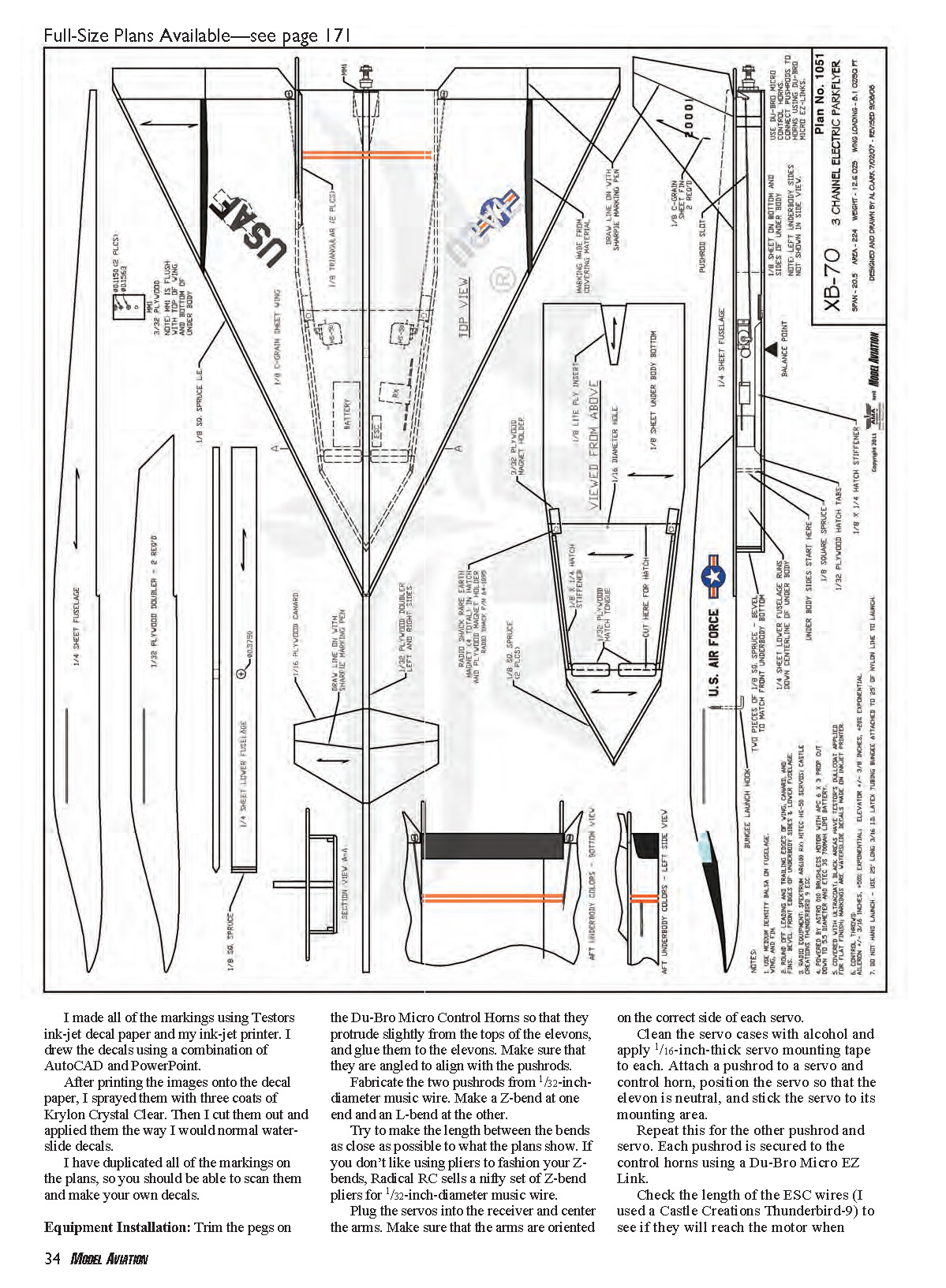
CONSTRUCTION
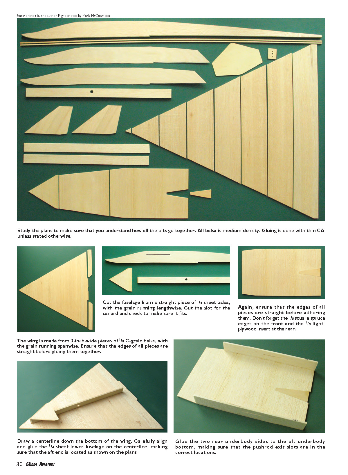
Study the plans to make sure you understand how all the bits go together. All balsa is medium density unless noted. Use thin CA for most gluing unless otherwise stated.
Parts, grain, and preliminary work
- Cut the fins from 1/8" C-grain balsa with the grain oriented vertically. Round the leading and trailing edges.
- Cut the fuselage from a straight piece of 1/4" sheet balsa with the grain running lengthwise. Cut the slot for the canard and check the fit.
- Add 1/8" square spruce edges on the front of the fuselage and a 1/8" light-plywood insert at the rear as shown on the plans.
- The wing is made from 3"-wide pieces of 1/8" C-grain balsa with the grain running spanwise. Make sure edges are straight before gluing.
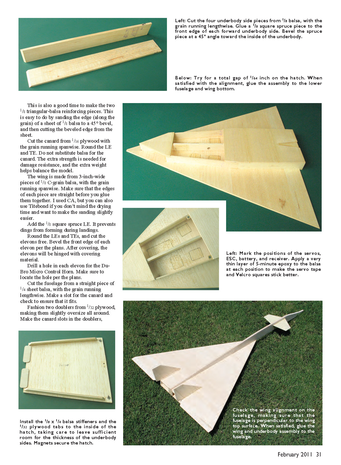
- Make two 1/8" triangular-balsa reinforcing pieces by sanding a 1/8" balsa sheet edge to a 45° bevel and cutting the beveled strip off.
Canard
- Cut the canard from 1/16" plywood with the grain running spanwise. Round the LE and TE. Do not substitute balsa for the canard — plywood adds damage resistance and useful nose weight.
- Add a 1/8" square spruce leading edge to prevent dings during landings.
Wing and elevons
- Round the wing LEs and TEs, and cut the elevons free. Bevel the front edge of each elevon per the plans. After covering, hinge the elevons with covering material.
- Drill a hole in each elevon for the Du-Bro Micro Control Horn and locate per the plans.
- Cut the elevon hinge gap and bevel as shown on the plans; after covering hinge with 1/2" strips of covering on top of the hinge line and 1/4" x 1/2" strips on the bottom at each end.
Underbody and hatch
- Cut four underbody side pieces from 1/8" balsa with grain lengthwise. Adhere a 1/8" square spruce to the front edge of each forward underbody side and bevel it 45° toward the inside as shown on the plans.
- Slice the pushrod exit slot into each rear underbody side. Make these slots slightly wider than 1/32" for good pushrod support.
- Build the bottom of the underbody like the wing (3" strips of 1/8" C-grain balsa, spanwise grain). Include 1/8" square spruce edges on the front and the 1/8" light-plywood insert at the rear.
- After trimming and sanding the bottom to outline, cut the hatch portion loose so you have three pieces for the underbody bottom.
- Draw a centerline down the bottom of the wing. Carefully align and glue the 1/4" lower fuselage on the centerline, ensuring the aft end matches the plans. Glue the forward piece of the underbody bottom to the 1/4" lower fuselage even with the front.
- Adhere the two rear underbody sides to the aft underbody bottom, locate the pushrod slots exactly, then center this assembly on the 1/4" lower fuselage using the hatch for fore-aft position. Aim for a total hatch gap of 1/64".
- Install two 3/32" plywood hatch magnet holders and glue RadioShack rare-earth magnets in place. Mark magnet locations on the hatch and recess magnets in the hatch with a 3/16" brass tube. Check magnet polarity before final gluing.
- Glue the hatch securely and add fillets where needed. Round the outer edges of the underbody per cross-section A-A on the plans.
Doublers and stiffeners
- Fashion two doublers from 1/32" plywood, slightly oversize. Make canard slots in the doublers.
- Install 1/8" x 1/4" balsa stiffeners and 1/32" plywood tabs to the inside of the hatch, leaving room for the thickness of the underbody sides. Magnets secure the hatch.
- Adhere the doublers to the fuselage with thick CA. When cured, sand doublers flush with the fuselage.
Final assembly steps
- Mark servo, ESC, battery, and receiver positions and apply a thin layer of 5-minute epoxy to the balsa at each position so servo tape and Velcro will adhere better.
- Position the two forward underbody sides and glue.
- Trial-fit the canard in the fuselage, adjust the slot if necessary, align, and glue.
- Check wing alignment so the fuselage is perpendicular to the wing top surface; when satisfied, glue the wing and underbody assembly to the fuselage.
- Drill firewall holes per the plans and check motor fit (I used an AstroFlight 010). Ensure the firewall contacts wing, lower fuselage, and underbody bottom so no unwanted thrust angles are built in. Use thick CA to secure the firewall.
- Mark and glue the two fins on the wing top, making sure they are perpendicular to the wing top surface with no left/right offset. Add the two 1/8" triangular-balsa reinforcing pieces.
- Fill any dings with spackle, sand smooth, round fuselage edges per cross-section A-A, and sand with 220 then 400 grit. Vacuum dust off before covering.
Covering and decals
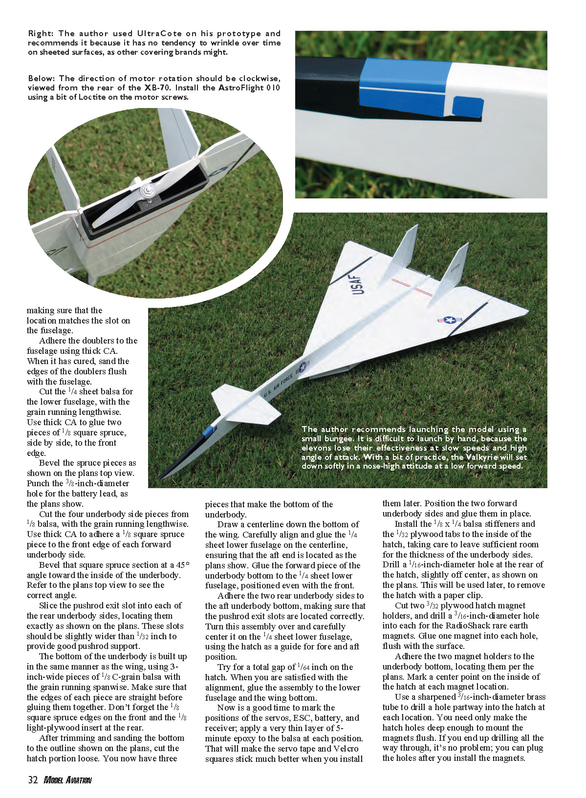
- I used Hangar 9 UltraCote because it tends not to wrinkle on sheeted surfaces. Iron the covering thoroughly to add strength.
- The black areas on the underbody and forward fuselage are UltraCote masked and sprayed with Testors ModelMaster DullCote flat paint. Windows were simulated with Sky Blue UltraCote; the correct outlines are on the plans. Make a paper copy of the window outlines, glue to UltraCote with rubber cement, cut out, remove the paper, and apply the windows.
- I cut the red stripes between the fins from UltraCote; stripe tape also works.
- After covering, hinge elevons as described above.
The author encourages builders to try aerobatics. Rolls are easy with full aileron; add a touch of down-elevator as it rolls through inverted.
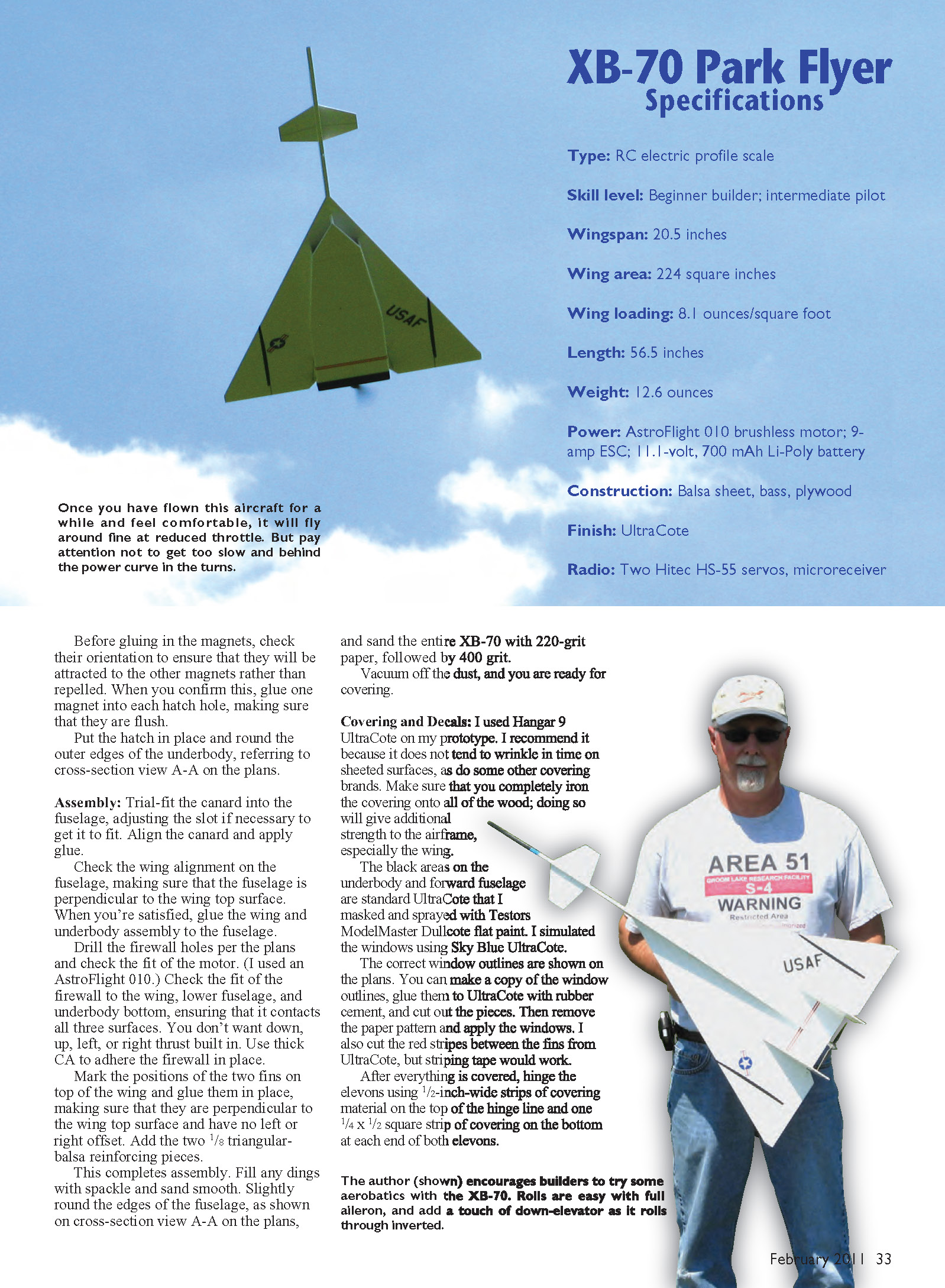
XB-70 Park Flyer Specifications
- Type: RC electric profile scale
- Skill level: Beginner builder; intermediate pilot
- Wingspan: 20.5 inches
- Wing area: 224 square inches
- Wing loading: 8.1 ounces/square foot
- Length: 56.5 inches
- Weight: 12.6 ounces (ready to fly)
- Power: AstroFlight 010 brushless motor; 9 A ESC; 11.1 V, 700 mAh Li-Poly battery
- Construction: balsa sheet, bass (basswood), plywood
- Finish: UltraCote
- Radio: Two Hitec HS-55 servos, micro receiver
I made the markings using Testors ink-jet decal paper and my ink-jet printer. I drew the decals in AutoCAD and PowerPoint, printed them, sprayed three coats of Krylon Crystal Clear, cut them out, and applied them like normal water-slide decals. The plans include all markings so you can scan and reproduce them.
EQUIPMENT INSTALLATION
- Trim the pegs on the Du-Bro Micro Control Horns so they protrude slightly from the tops of the elevons and glue them in place, angled to align with the pushrods.
- Fabricate two pushrods from 1/32" music wire with a Z-bend at one end and an L-bend at the other. Try to match the lengths on the plans. (Radical RC sells Z-bend pliers if needed.)
- Plug servos into the receiver and center the arms; orient arms on the correct side of each servo. Clean servo cases with alcohol and apply 1/16" servo mounting tape to each.
- Attach a pushrod to a servo and control horn, position the servo so the elevon is neutral, and stick the servo to its mounting area. Repeat for the other servo. Secure pushrods to control horns using Du-Bro Micro EZ Links.
- Check ESC wire length (I used a Castle Creations Thunderbird-9) and add length if necessary. Solder motor wires to the motor and plug the ESC into the receiver. Motor rotation should be clockwise when viewed from the rear of the XB-70.
- Install the motor with a bit of Loctite on the screws. Install the ESC and receiver with Velcro self-adhesive squares.
- Trim an APC 6x3 prop to 5.5" diameter, balance it, and install it on the motor. Ensure the front of the blades face forward.
- Adhere two Velcro pieces to the bottom of the wing where the battery sits. Glue 1/4" square balsa stops at the front and rear of the battery to prevent fore/aft movement. Run the battery lead through the hole in the lower fuselage to connect to the ESC.
- Drill a small hole in the bottom of the forward fuselage and screw in an “L” hook (from a hardware store). Remove, epoxy in place, and reinstall. Install the hatch cover.
- Check the balance point. If nose weight is required, make a small pocket in the forward fuselage from the bottom and glue weight in place; cover it with covering material. If tail weight is required, glue it inside the underbody at the rear.
- Set elevon throws per plans note #6. The elevons have no reflex at neutral (0°). Set exponential for elevator and aileron near 20%. Verify elevons move correctly for both elevator and aileron commands.
FLYING
Initial flights were challenging. On the first flights the model rolled opposite to commanded turns and became uncontrollable at high angles of attack, resulting in a crash into a pond. The airframe dried out and most electronics survived except the ESC.
After analysis I determined the profile fuselage created too much fin area ahead of the balance point, making the model under-finned. I scaled the fin area up by 50% (same proportions). Larger fins cured the problem; the plans and flight photos show the larger fins.
Launch and takeoff
- I recommend a small bungee launch. Hand launches are difficult because elevons are ineffective at slow speeds and high angles of attack.
- Make a bungee that provides 5–6 pounds of pull (I used yellow surgical tubing 7/32" OD, 1/8" ID, 25' long, attached to 25' of braided nylon line).
- Launch from a small flat surface angled up about 20° (card table, cardboard box, etc.) so the Valkyrie clears the grass. Attach the bungee to the model, start with power off, and as soon as it clears the box power up and fly.
- At release go to full throttle and hold roughly one-third up-elevator. Be ready for a quick pitch-up as speed increases and elevons become effective; then go to neutral elevator.
Flight characteristics and aerobatics
- The XB-70 is fairly quick. Use modest rates for initial flights; it will roll rapidly with high rates.
- Avoid climbing too steeply; a shallow climb works best. If the nose gets too high drag increases and the model can lose speed and “get behind the power curve.” At that point elevons become ineffective and the model may roll and spiral. Recovery requires letting it dive to regain speed and needs altitude.
- Attain a comfortable altitude, set trims for level flight, and avoid flying too far out on first flights; orientation can be difficult when the thin wing is edge-on.
- Have someone call out when 4 minutes has passed so you can set up for landing while there is still battery.
- The model will fly dead-stick but comes down fast and with little flare without power.
- For aerobatics:
- Rolls: full aileron, add a touch of down-elevator as it rolls through inverted.
- Loops: start level at full throttle, set up a shallow dive and pull full up-elevator for a loop (a bit of dive is required).
Landing
- Land into the wind with a little power to slow speed. Touchdown is on the fuselage with the canard up to cushion the landing.
- The aircraft tends to porpoise if you reduce power too early — add a touch of power if it noses over on touchdown.
- A smooth flare (throttle back and add up-elevator for a nose-high flare) gives the best results. Cut power immediately before touchdown to avoid breaking the propeller.
Repairs
- Repairs are easy. For torn wing covering apply a covering patch and re-glue torn balsa with thin CA. For fuselage damage strip covering back, add reinforcement, and re-cover. The 1/16" plywood canard rarely needs repair.
Thanks to Mark McCutcheon for the flight photos.
Enjoy the Valkyrie — it looks great in the air and is a good conversation piece at the flying field. Read up on the XB-70 history; you'll get many questions when people see you flying yours.
Sources
- AstroFlight — (949) 855-9903 — www.astroflight.com
- Du-Bro — (800) 848-9411 — www.dubro.com
- RadioShack — (800) 843-7422 — www.radioshack.com
- UltraCote (Hangar 9) — (800) 338-4639 — www.hangar-9.com
- Radical RC — (937) 256-7727 — www.radicalrc.com
- Castle Creations — (913) 390-6939 — www.castlecreations.com
- APC — (530) 661-0399 — www.apcprop.com
- Testors — (800) 837-8677 — www.testors.com
Transcribed from original scans by AI. Minor OCR errors may remain.

