
Your Propeller & You
MOST COMPETITIVE events have reached a state of sophistication that requires complete control of every function. The one function that has been very slow to receive much attention has been the propeller. Luckily, the prop manufacturers have done a good job in providing the competitive modeler with not only a wide selection, but also some very well designed propellers.
Wood propellers are generally the most popular props for competition, although in some events cast fiberglass props are quite popular. Nylon propellers are usually reserved for the sport flyer. The selection of a propeller material is usually determined by two things; namely, the application and economics. In events where high engine performance is essential, nylon props are rarely used. This is due to the fact that the nylon prop may fail at high rpms and can do severe bodily injury or damage to equipment. In addition, the nylon propeller tends to flatten out and lose pitch in time, whereas the fiberglass or wood prop will not. On the other hand, it is impractical for the sport flyer to use a $5.00 fiberglass prop or to break a $1.00 wood prop on each landing. The nylon prop is by far his best bet.
Ironically, the molded nylon prop, including those that are fiberglass filled, because of their manufacturing techniques, are the most consistent performers. The weights, thicknesses, balance and pitch of all similar nylon props are essentially identical. This is, however, not true of most wood or cast fiberglass props. The wood props are machined and the dimensions will vary with the different pieces of wood used as blanks and, also, with machining tolerances. Fiberglass props are usually cast by hand in a very time-consuming process. Because of this, the dimensions of these props will vary all over the map from one prop to another.
It is the intent of this article to describe the processes involved to standardize cast fiberglass and wood propellers. I do not intend to tell you what dimensions you should use for your individual application. This is up to you to determine by trial and error. There are five critical factors to standardizing props: diameter, pitch, blade width, blade thickness, and balance. In addition, other factors include blade design and airfoil.
Most of the factors can be quickly reduced to a ballpark range through either availability or trial and error. For instance, if you fly FAI free flight you know you need about a 7-3 prop, and you want to eliminate possible breakage, so you choose a fiberglass prop. There are only a couple available brands of fiberglass 7-3 props, so you are limited pretty much right there. Through trial and error on a couple of props you try various blade pitches (say 7-2, 7-2½, 7-3, 7-3½) and various blade thicknesses. You decide on a set of dimensions and henceforth rework all future props to these previously determined dimensions.
On the other hand, if you fly CL B Speed you know that you need about a 7-10 prop. You don't want fiberglass because you usually ruin the prop on each landing and, if nothing else, the cost is prohibitive. You select several props of each available brand of basic 7-10 wood prop (say 7-9, 7-9½, 7-10, 7-10½) and, again through trial and error, determine the best basic design for your application. You then determine the set of dimensions you want on future props and either inspect and reject enough production props to supply you with your requirements or rework them to your own individual specifications.
The tool required to properly inspect a propeller are a pitch gauge, calipers or micrometer, and a prop balancer. These three basic tools combined with various files and sandpaper, plus plenty of time, will give you consistent performance from your propeller.
First you need a pitch gauge. There are a couple of fine gauges which you can purchase for $20.00 to $30.00 at your local hobby shop, or you can build the one accompanying this article for less than $2.00 and about two hours of time. Either way, you must have a means of determining propeller pitch. With a pitch gauge you are measuring the theoretical pitch. The actual pitch of the prop varies with blade velocity (rpm) and airplane velocity (forward speed), plus other factors.
To operate the pitch gauge, mount the prop in the mounting block and align it so that it is perpendicular to the slots and tighten the locking screw or nut. Next, put the mounting block in the first station, usually the shortest radius, or slot "A." Then, bring the pointer up so that it contacts the underside of the propeller. By sliding the block forward or backward, adjust it so that it is in contact over the entire width of the blade. Mark off this location with a pencil or pen on the prop blade for that slot or station on each blade. Then, at that station, check and record the pitch on each blade. The pitch is merely the angle of the blade converted to linear motion per revolution for that particular radius. As shown in Fig. No. 1, Pitch = 2 x Radius x Tangent of the Angle. Therefore, as you increase the angle you increase the pitch, or vice versa. The pitch gauge is merely a protractor used for measuring the angle, with the scale converted to pitch at each station.
If you encounter a situation where the bottom of the prop blade is not exactly flat, the safest bet is to file it flat before going any further. If the pitch is not what you want, file or sand that station to the desired value. Each corresponding station on both blades should be the same. Previous experience has shown me that if you can balance the pitch between blades at each station within +/- 1/4 inch, that will be close enough. You may also find that the blade pitch is not consistent over the entire blade length. It may vary from, say, a 4-in. pitch at the hub to a 6-in. pitch at the tips. This is perfectly O.K. as long as both blades are consistent with one another.
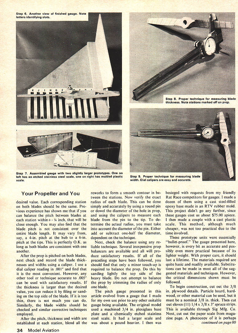
After the prop is pitched on both blades, next check and record the blade thicknesses and widths using a caliper. I use a dial caliper reading in .001" and find that it is the most convenient. However, any other tool or technique accurate to .005" can be used with satisfactory results. If the thickness is larger than the desired value, you can reduce it by filing or sanding on the top side of the blade. If it is too thin, there is not much you can do. Similarly, the blade widths should be checked and similar corrective techniques employed.
After the pitch, thickness and width are established at each station, blend all the reworks to form a smooth contour in between the stations. Now verify the exact radius of each blade. This can be done simply and accurately by using a round pin or dowel the diameter of the hole in prop, and using the calipers to measure each blade from the pin to the tip. To determine the actual radius, you must take into account the diameter of the pin. Either add or subtract one-half the diameter, dependent on the technique.
Next, check the balance using any reliable technique. Several inexpensive prop balancers are available and all will produce satisfactory results. If all of the preceding steps have been followed, you should find that only a minor touch-up is required to balance the prop. Do this by sanding lightly the top side of the heavy blade. Do not attempt to balance the prop by trimming the radius of only one blade.
The pitch gauge presented in this article evolved from a gauge that I made for my own use prior to any other suitable gauge being available. The original model used a machined 3/4 in. plexiglass base plate and a chemically etched stainless steel scale. It had a larger scale and was about a pound heavier. I then was besieged with requests from my friendly Rat Race competitors for gauges. I made a dozen of them using a cast steel-filled epoxy base made in an RTV rubber mold. This project didn't go any further, since these gauges cost us about $75.00 apiece. I then made a couple with a cast plastic scale. This method, although much cheaper, was not too practical due to the time involved.
These prototype units were essentially "bullet-proof." The gauge presented here, however, is every bit as accurate and possibly even more practical because of its lighter weight. With proper care, it should last a lifetime. The materials required are quite basic and readily available. Substitute items can be made in most all of the suggested materials and techniques. However, the critical dimensions shown must be followed.
To begin construction, cut out the 3/8 in. plywood details. Particle board, hard- wood, or other material can be used, but it must be a nominal 3/8 in. thick. Then cut out eleven (11) 1/4 x 3/8 x 3/8 in. spruce strips. This is available through Sig Mfg. Co. Next, cut out the paper scale from magazine page. A photocopy of it is perhaps
Your Propeller and You
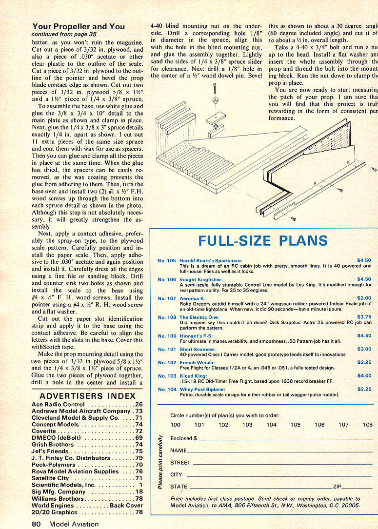
better, as you won't ruin the magazine. Cut out a piece of 3/32 in. plywood, and also a piece of .030" acetate or other clear plastic to the outline of the scale. Cut a piece of 3/32 in. plywood to the outline of the pointer and bevel the prop blade contact edge as shown. Cut out two pieces of 3/32 in. plywood 5/8 x 1½" and a 1½" piece of 1/4 x 3/8" spruce.
To assemble the base, use white glue and glue the 3/8 x 3/4 x 10" detail to the main plate as shown and clamp in place. Next, glue the 1/4 x 3/8 x 3" spruce details exactly 1/4 in. apart as shown. I cut out 11 extra pieces of the same size spruce and coat them with wax for use as spacers. Then you can glue and clamp all the pieces in place at the same time. When the glue has dried, the spacers can be easily removed, as the wax coating prevents the glue from adhering to them. Then, turn the base over and install two (2) #1 x 1/2" F.H. wood screws up through the bottom into each spruce detail as shown in the photo. Although this step is not absolutely necessary, it will greatly strengthen the assembly.
Next, apply a contact adhesive, preferably the spray-on type, to the plywood scale pattern. Carefully position and install the paper scale. Then, apply adhesive to the .030" acetate and again position and install it. Carefully dress all the edges using a fine file or sanding block. Drill and counter sink two holes as shown and install the scale to the base using #4 x 1/2" F. H. wood screws. Install the pointer using a #4 x 1/2" R. H. wood screw and a flat washer.
Cut out the paper slot identification strip and apply it to the base using the contact adhesive. Be careful to align the letters with the slots in the base. Cover this with Scotch tape.
Make the prop mounting detail using the two pieces of 3/32 in. plywood 5/8 x 1½" and the 1/4 x 3/8 x 1½" piece of spruce. Glue the two pieces of plywood together, drill a hole in the center and install a 4-40 blind mounting nut on the underside. Drill a corresponding hole 1/8" in diameter in the spruce, align this with the hole in the blind mounting nut, and glue the assembly together. Lightly sand the sides of 1/4 x 3/8" spruce slider for clearance. Next drill a 1/8" hole in the center of a 1/4" wood dowel pin. Bevel this as shown to about a 30 degree angle (60 degree included angle) and cut it off to about a 1/2 in. overall length.
Take a 4-40 x 3/4" bolt and run a nut up to the head. Install a flat washer and insert the whole assembly through the prop and thread the bolt into the mounting block. Run the nut down to clamp the prop in place.
You are now ready to start measuring the pitch of your prop. I am sure that you will find that this project is very rewarding in the form of consistent performance.
MOST COMPETITIVE events have reached a state of sophistication that requires complete control of every function. The one function that has been very slow to receive much attention has been the propeller. Luckily, the prop manufacturers have done a good job in providing the competitive modeler with not only a wide selection, but also some very well designed propellers. Wood propellers are generally the most popular props for competition, although in some events cast fiberglass props are quite popular. Nylon propellers are usually reserved for the sport flyer.
The selection of a propeller material is usually determined by two things; namely, the application and economics. In events where high engine performance is essential, nylon props are rarely used. This is due to the fact that the nylon prop may fail at high rpms and can do severe bodily injury or damage to equipment. In addition, the nylon propeller tends to flatten out and lose pitch in time, whereas the fiberglass or wood prop will not. On the other hand, it is impractical for the sport flyer to use a $5.00 fiberglass prop or to break a $1.00 wood prop on each landing. The nylon prop is by far his best bet. Ironically, the molded nylon prop, including those that are fiberglass filled, because of their manufacturing techniques, are the most consistent performers. The weights, thicknesses, balance and pitch of all similar nylon props are essentially identical. This is, however, not true of most wood or cast fiberglass props.
The wood props are machined and the dimensions will vary with the different pieces of wood used as blanks and, also, with machining tolerances. Fiberglass props are usually cast by hand in a very time-consuming process. Because of this, the dimension of these props will vary all over the map from one prop to another. It is the intent of this article to describe the processes involved to standardize cast fiberglass and wood propellers. I do not intend to tell you what dimensions you should use for your individual application. This is up to you to determine by trial and error. There are five critical factors to standardizing props: diameter, pitch, blade width, blade thickness, and balance. In addition, other factors include blade design and airfoil. Most of the factors can be quickly reduced to a ballpark range through either availability or trial and error. For instance, if you fly FAI free flight you know you need about a 7-3 prop, and you want to eliminate possible breakage, so you choose a fiberglass prop. There are only a couple available brands of fiberglass 7-3 props, so you are limited pretty much right there. Through trial and error on a couple of props you try various blade pitches (say 7-2, 7-2½, 7-3, 7-3½) and various blade thicknesses. You decide on a set of dimensions and henceforth rework all future props to these previously determined dimensions.
The tools required to properly inspect a propeller are a pitch gauge, calipers or micrometer, and a prop balancer. These three basic tools combined with various files and sandpaper, plus plenty of time, will give you consistent performance from your propeller.
First you need a pitch gauge. There are a couple of fine gauges which you can purchase for $20.00 to $30.00 at your local hobby shop, or you can build the one accompanying this article for less than $2.00 and about two hours' work.
Transcribed from original scans by AI. Minor OCR errors may remain.

