
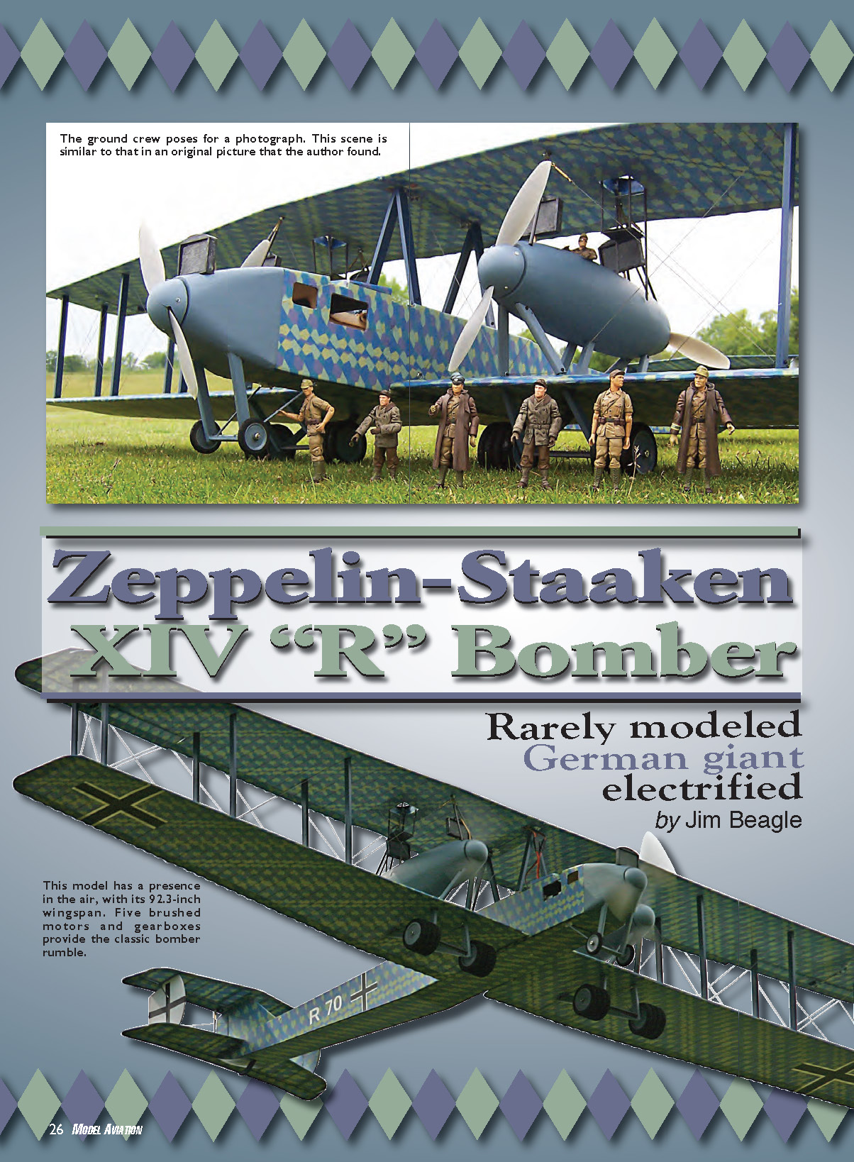
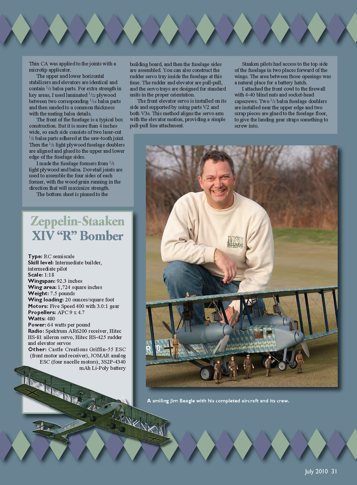

Zeppelin-Staaken XIV "R" Bomber
- Rarely modeled
- German giant
- Electrified
- By Jim Beagle
“R-planes” were the German giants of the Great War. The “R” stood for Riesenflugzeug, which translates to “giant aeroplane.” These strategic bombers were a result of Ferdinand Graf von Zeppelin’s ambitions and imagination.
He had realized how vulnerable his large dirigible airships would be as soon as airplanes could reach them. Zeppelin took advantage of the great space available in the airship sheds and built most of these bombers at the Berlin suburb of Staaken.
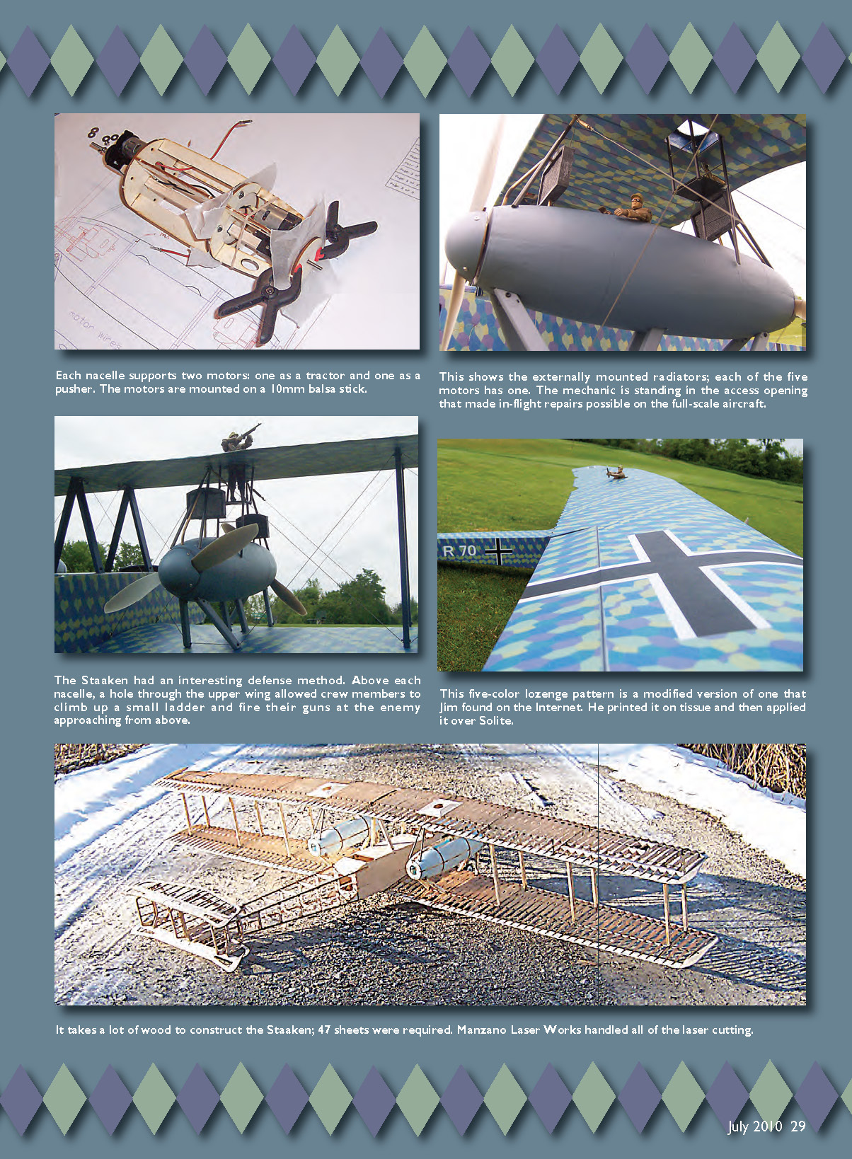
Zeppelin-Staaken engines were housed in nacelles large enough for mechanics to make in-flight repairs by literally working within each gondola. The massive 18-wheel undercarriage had to bear enormous weights, with huge 1,000-kilogram bombs. A ground staff of 42 was required just to get the aircraft out of the hangar.
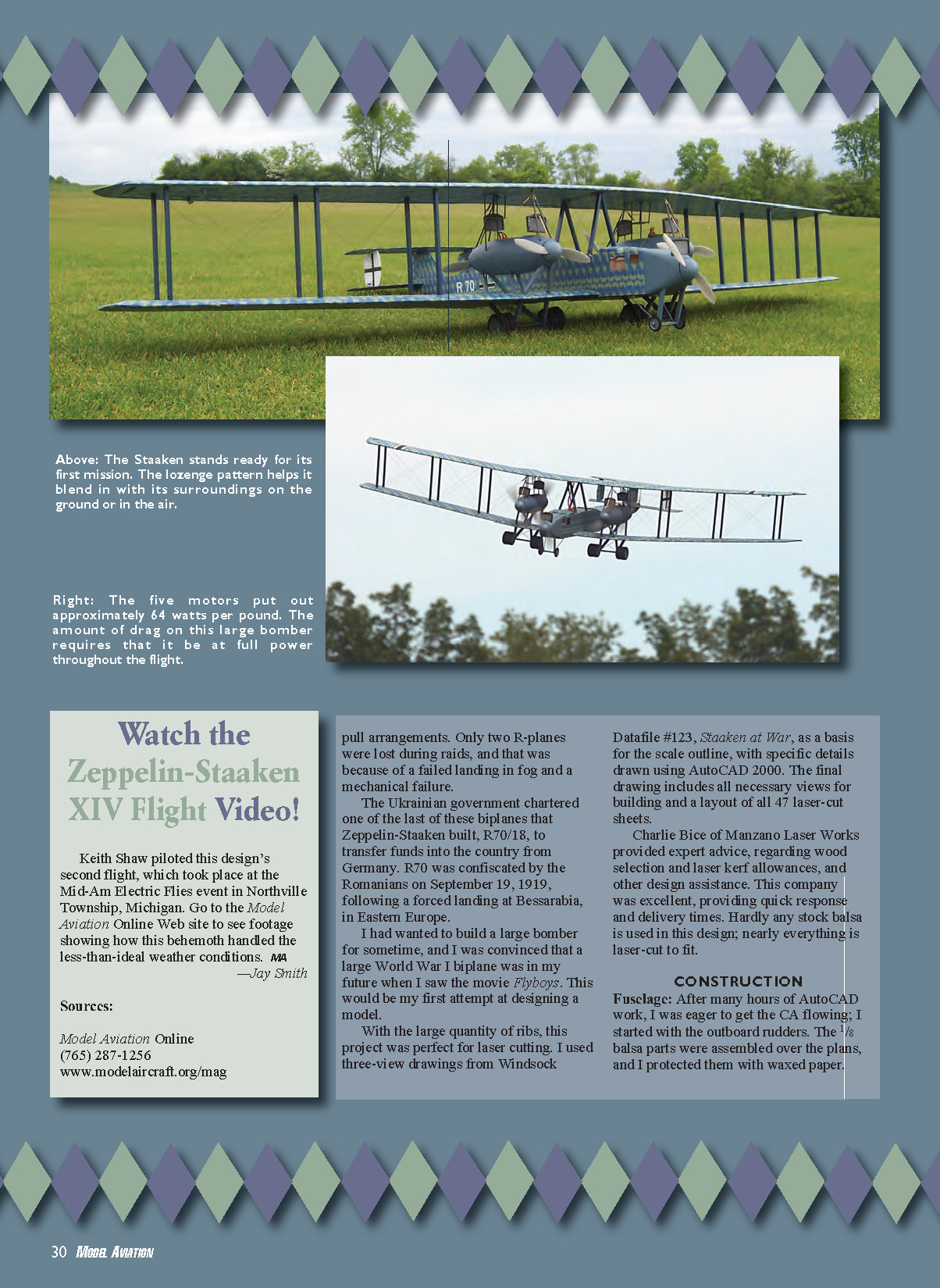
The Staaken was difficult to shoot down, thanks to its size, defensive guns, and the security provided by its five engines in tandem push-pull arrangements. Only two R-planes were lost during raids, and those losses resulted from a failed landing in fog and a mechanical failure.
One of the last biplanes Zeppelin-Staaken built, R70/18, was chartered by the Ukrainian government to transfer funds into the country from Germany. R70/18 was confiscated by the Romanians on September 19, 1919, following a forced landing in Bessarabia, in Eastern Europe.
I had wanted to build a large bomber for some time, and I was convinced a large World War I biplane was in my future when I saw the movie Flyboys. This would be my first attempt at designing a model.
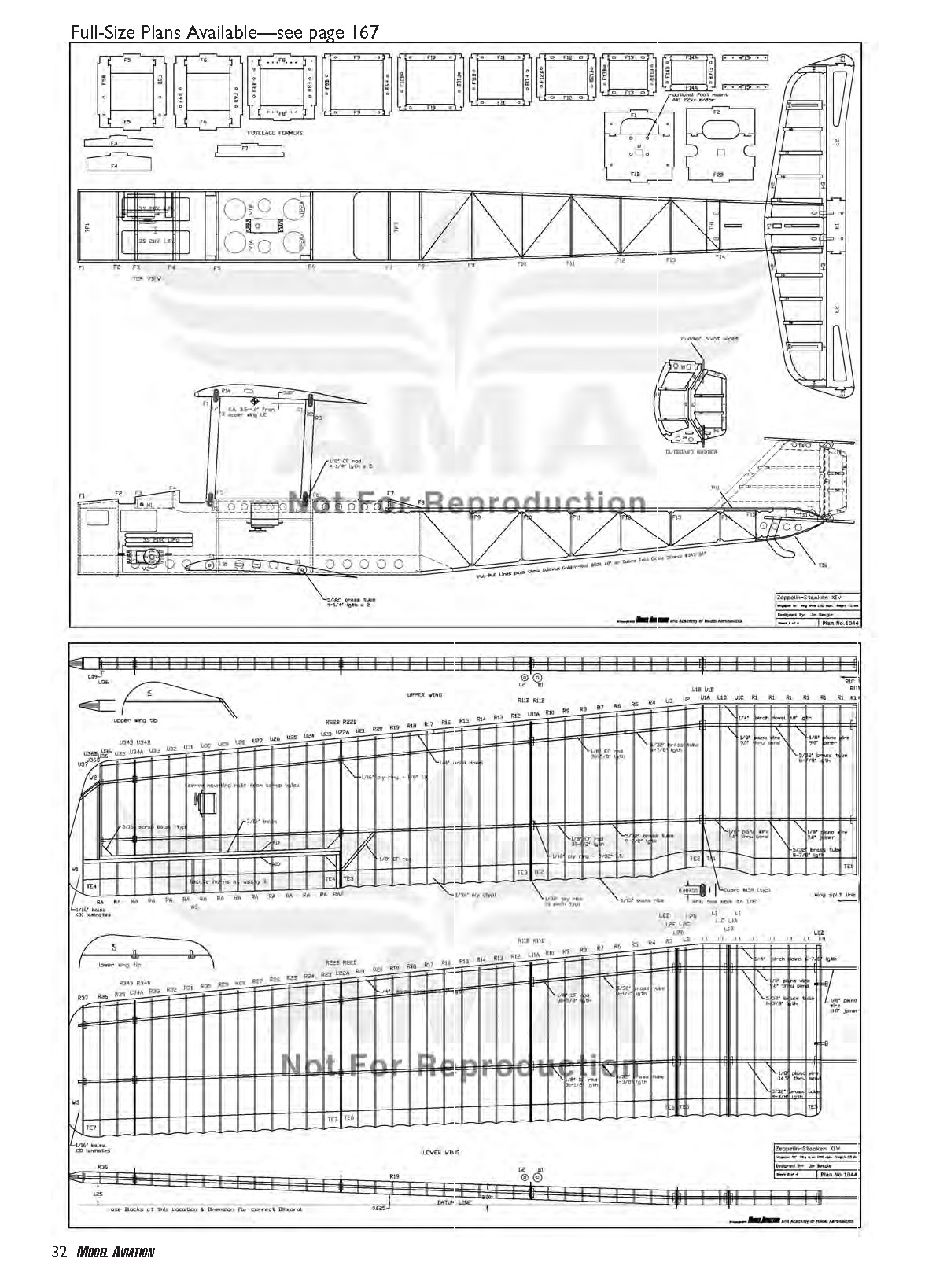
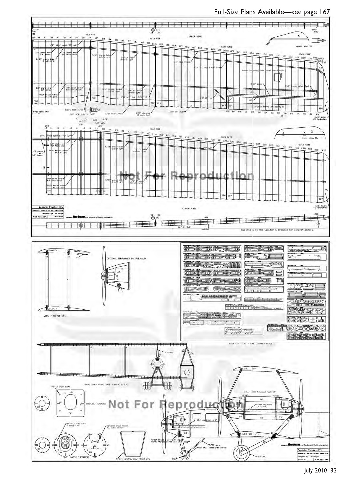
With the large quantity of ribs, this project was perfect for laser cutting. I used three-view drawings from Windsock Datafile #123, Staaken at War, as a basis for the scale outline, with specific details drawn using AutoCAD 2000. The final drawing included all necessary views for building and a layout of all 47 laser-cut sheets.
Charlie Bice of Manzano Laser Works provided expert advice regarding wood selection, laser kerf allowances, and other design assistance. This company was excellent, providing quick response and delivery times. Hardly any stock balsa is used in this design; nearly everything is laser-cut to fit.
CONSTRUCTION
Fuselage
After many hours of AutoCAD work, I was eager to get the CA flowing. I started with the outboard rudders. The 1/8-inch balsa parts were assembled over the plans and protected with waxed paper. Thin CA was applied to the joints with a microtip applicator.
The upper and lower horizontal stabilizers and elevators are identical and contain 1/8-inch balsa parts. For extra strength in key areas, I used laminated 1/32-inch plywood between two corresponding 1/16-inch balsa parts and then sanded to a common thickness with the mating balsa details.
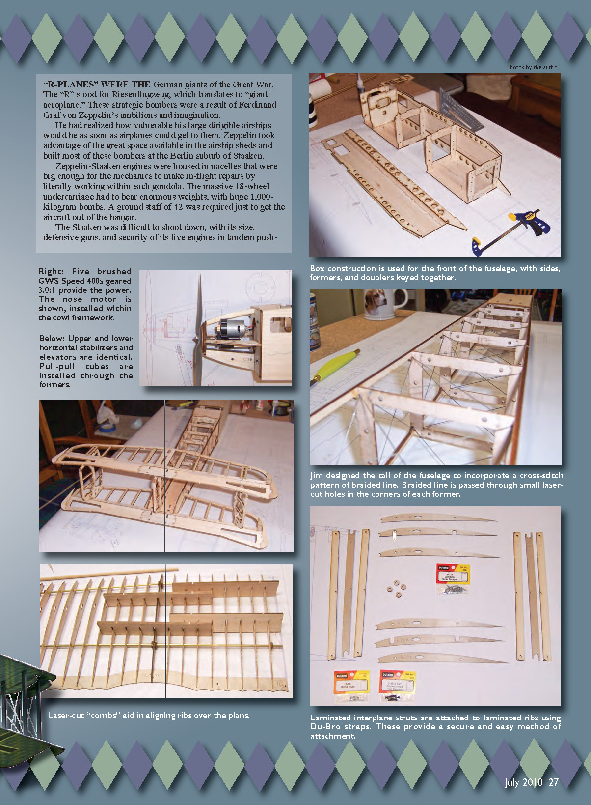
The front of the fuselage is a typical box construction, but it is more than 4 inches wide, so each side consists of two laser-cut 1/8-inch balsa parts adhered at the saw-tooth joint. Then the 1/8-inch light plywood fuselage doublers are aligned and glued to the upper and lower edges of the fuselage sides.
I made the fuselage formers from 1/8-inch light plywood and balsa. Dovetail joints are used to assemble the four sides of each former, with the wood grain running in the direction that maximizes strength.
The bottom sheet is pinned to the building board, and then the fuselage sides are assembled. You can also construct the rudder servo tray inside the fuselage at this time. The rudder and elevator are pull-pull, and the servo trays are designed for standard units in the proper orientation.
The front elevator servo is installed on its side and supported by parts V2 and both V3s. This method aligns the servo arm with the elevator motion, providing a simple pull-pull line attachment.
Staaken pilots had access to the top side of the fuselage in two places forward of the wings. The area between those openings was a natural place for a battery hatch.
I attached the front cowl to the firewall with 4-40 blind nuts and socket-head capscrews. Two 1/8-inch balsa fuselage doublers are installed near the upper edge and two scrap pieces are glued to the fuselage floor to give the landing gear straps something to screw into.
I wanted the Staaken to be powered by five brushed motors and gearboxes for that classic bomber rumble. The GWS gearboxes are designed for 10mm square hard balsa sticks, which PB Hobbies sells in 12-inch lengths.
The position of the gearbox was adjusted to provide clearance between the cowl and the 1/8-inch light plywood spinner backplate. The diameter of the GWS 400 motor interferes slightly with the top stringer of the cowl frame, which must be sanded to fit.
After I verified the clearances, I epoxied the motor stick in place. The model's cowl was created using four blue-foam blocks, adhered into the cowl frame with aliphatic glue.
I employed a belt sander, then a coarse-grit sandpaper block, and then a 220-grit sanding bar to achieve the desired shape. The interior was opened up with a drum sander on an electric rotary tool.
The Staaken XIV employed two undercarriage legs with fairings to support the front axle. The front legs are two light-plywood struts laminated together. The front axle is also supported from the rear with a 7/32-inch-diameter wire, bent to shape over the plans.
I sanded a groove into the underside of the foam cowl in the area around the landing gear attachment rod. The strut attachment is a 5/32-inch-diameter brass rod inserted through the cowl's laminated stringers and epoxied in place.
A 4-40 threaded rod then passes through the brass bushing. The front landing gear assembly was temporarily clamped in position to verify locations. I added two scrap pieces of light plywood and glued them between the fairings for a bit more strength.
The area around the landing gear is filled with spackle and sanded smooth. The 3/32-inch wire axle, rear landing gear wire, and axle plate are lashed together using braided musky fishing line.
I fabricated the tail end of the fuselage from four 1/8-inch basswood laser-cut stringers. The basswood stringers are glued to the rear fuselage side and then glued to the front fuselage box. The formers are each assembled into notches in the basswood stringers.
The tail assembly is built over the plans. I soaked the 1/16-inch balsa parts with water, bent them into a curve, and let them dry for a few hours.
The tail of the fuselage was designed to incorporate a cross-stitch pattern of braided line. Starting on the bottom side of the fuselage box, I passed the braided line through small laser-cut holes in the corners of each former. I stretched each string segment taut and wicked thin CA into the hole to hold the string in place. I applied a drop of thick CA after the second string was passed through each hole, and then I sprayed kicker while holding the braided line tight.
The crisscross pattern of braided line greatly improved the rigidity of the fuselage while maintaining a lightweight structure. Plastic tubes are threaded through the laser-cut holes in each former for pull-pull lines to pass through.
Wings
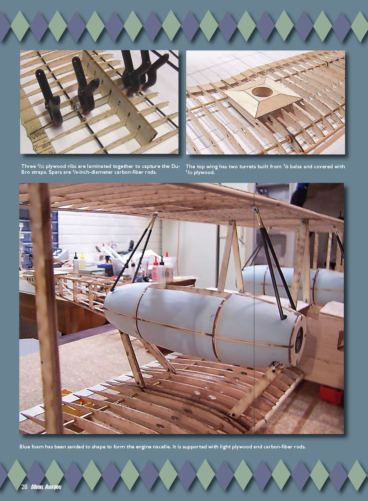
A unique attachment method is used on the wing struts. Metal landing gear straps (Du-Bro item 158) are laminated between two 1/32-inch plywood ribs. A third plywood rib in the middle is used to align and keep the strap in place.
One end of the Du-Bro strap is drilled out to 1/8 inch in diameter for a carbon-fiber spar to pass through. Then the interplane struts can be attached to the straps with #2-56 blind nuts and socket-head capscrews.
Starting with one side of the upper wing, I constructed the spars from 1/8-inch-diameter carbon-fiber rods cut to length. The rods slide into 5/32-inch brass tubing, per the plans. Two short sections of wire are bent over the plans to join the two sections of brass.
The trailing edge is pinned to the board over the plans. The balsa ribs are "skewered" onto the rear spar, like a shish kebab. Four laser-cut rib-alignment combs are utilized to help keep things straight during assembly. I used thin CA to glue the ribs to the trailing edge and then adhered the ribs to the rear spar with a drop of thick CA.
The laminated ribs are not glued until the upper wing has been removed from the board. The front carbon-fiber rod spar is inserted through the ribs, and the process is completed from root to tip.
The 1/4-inch balsa dowel leading edge (LE) is glued to each rib. After all 1/16-inch balsa ribs are glued, I flipped the wing over and aligned the Du-Bro straps between each of the three 1/32-inch plywood ribs, clamped them together, and wicked CA into the edges. Then I glued the "doughnuts" onto each side of the laminated ribs for lateral strength.
Aileron ribs are keyed into the hinge line. The aileron tip is three pieces of 1/16-inch balsa, laminated and sanded into a classic wingtip profile. The ribs are not thick enough to fully install the Hitec HS-81 servo and enclose it with a hatch, but the servos are unobtrusive with the wing undercamber.
The Du-Bro straps point up on the bottom wing, so the three plywood ribs can be assembled directly on the board. The ribs are assembled using the same methods as on the upper wing.
Although the lower wing does not have ailerons, it has other design and building challenges. In addition to the swept-back portion, it has 2° of dihedral.
The outer section of the wing is supported on blocks at the appropriate angle, and the joiner wires are bent per the plans. Strut ribs in this section support the landing gear below and the nacelle above, so there are five ribs laminated together to get the correct angle for the Du-Bro straps.
The Staaken had an interesting method of defense. Above each nacelle was a hole through the upper wing; the crew could climb up a small ladder and fire the guns at an enemy approaching from above. I wouldn't have thought that the safest position with a Bristol Fighter coming down on you!
The turret box is framed with scrap balsa; the box protrudes above the ribs by 1/8 inch all around. The turret fairings and cap are built from custom-fit 1/32-inch plywood.
The 36-inch servo extensions are threaded through the rib holes in the upper wings, and 12-gauge motor wires are installed in the lower wings. Scrap balsa is added to the area where the wires will come out of the wing covering.
I built the nacelle struts using four balsa lengths that create a hollow center through which the motor wires pass. The center of each interplane strut is 1/32-inch plywood and captures the end of the Du-Bro strap. The center-section is sandwiched between two pieces of 1/8-inch light plywood, glued, and clamped together.
Nacelles
The nacelles are similar in construction to the cowl, with 1/8-inch light plywood forming the skeleton of the structure. I cut the 10mm x 10mm balsa stick to length and installed it in the center nacelle section but did not glue it, allowing the GWS 400 motor gearbox to be temporarily mounted.
I glued four 4-40 blind nuts into the firewall and then attached the cowling baseplate with 4-40 1/2-inch bolts. I dry-assembled the cowl front plate with stringers, then centered the spinner backplate onto the prop shaft and clamped it into position.
After checking that all parts were seated, centered, and square, I glued the assembly together. You can flesh out the nacelles by adhering four sections of blue foam in place and then sanding to shape.
I glued a paper copy of the nacelle cross-sectional view onto a piece of fan-fold foam to use as a fixture spacer between the lower wing and the nacelle to ensure the proper incidence. The lower strut attachment points have a similar construction as the front cowling, using the Du-Bro straps with 4-40 threaded rod.
Final Fit and Assembly
The center rudder is of conventional design with CA hinges, but the outboard rudders are "balanced." I inserted two short lengths of music wire into each end of the rudder. These plug into short lengths of brass tubing that are epoxied into the upper and lower horizontal stabilizers, thereby allowing the rudders to pivot.
The center wing struts attach to four points on top of the fuselage. Du-Bro metal landing gear straps are bent at a 30° angle toward the center.
The carbon-fiber rod and straps are assembled in place. Lower wing spars plug into the brass tubes that span the fuselage. Fuselage struts meet at the center of the top wing and capture a Du-Bro strap on each spar.
The carbon-fiber rods and doughnuts are aligned and glued into the fuselage. Nacelles are again assembled to the lower wing.
Nacelle struts going to the top wing are made from 3/32-inch-diameter wire slid into lengths of 4mm carbon-fiber tube. A short length of brass tube is pinched at the top of the struts, and 2-56 bolts are attached through the Du-Bro strap.
Finishing
I fiberglassed the nacelles with 3/4-ounce cloth and used water-based polyurethane mixed with baby powder to fill the weave. Two more coats were needed to get a smooth surface.
I added several panel lines using 1/16-inch pin-striping. Struts and nacelles were painted with Model Master Intermediate Blue. The interplane struts were painted with Blue Angel Blue.
Unable to find propeller spinners that were the appropriate shape, I happened upon some plastic Easter eggs in the grocery store that would work. Each egg had a small package of chocolates inside, so I had to buy a few extra. Yum!
The backplate is 1/8-inch light plywood laser-cut to 2 inches in diameter. Four 1/4 x 3/8-inch balsa blocks are glued and sanded to fit the interior egg profile. Then I used a rotary tool to cut the eggs to the correct size.
My propeller shafts are threaded, so I used four small button-head screws to attach the spinner after mounting the propellers.
Covering
Some Zeppelin-Staaken bombers had lozenge covering with large polygons of irregular patterns that were hand-painted on the airframe. The R70/18 model used the conventional five-color, top-side lozenge fabric that was preprinted and used on other biplanes of the era.
However, at a scale of 1:18 the lozenge fabric squares would be only about 3 inches wide. To put this into perspective, there are roughly 75 polygons in a 3 x 3-inch area; that level of detail would be impractical to reproduce at this scale, so I used the conventional preprinted lozenge fabric.
Transcribed from original scans by AI. Minor OCR errors may remain.

