
ZOOMER
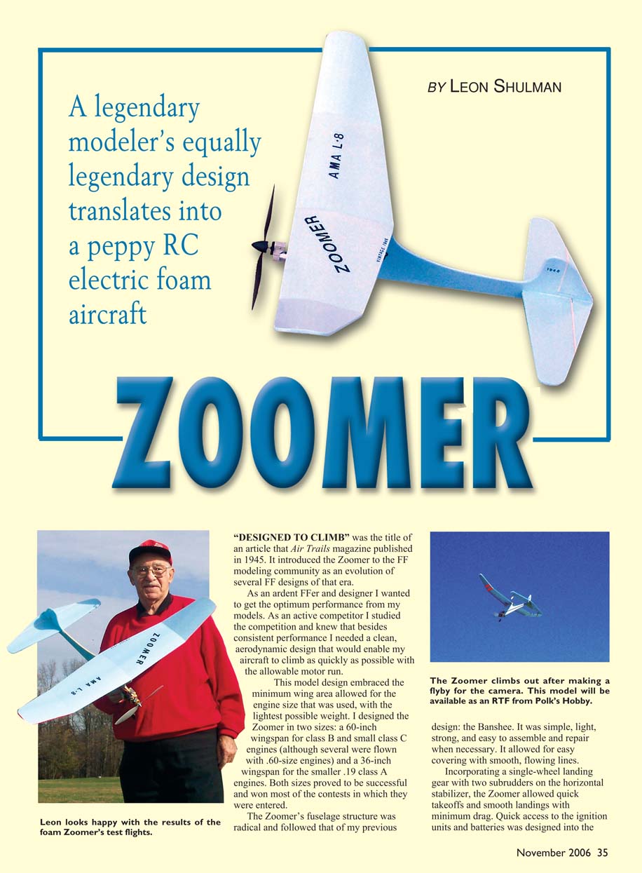
A legendary modeler’s equally legendary design translates into a peppy RC electric foam aircraft
By Leon Shulman
Introduction and history
"Designed to Climb" was the title of an article Air Trails published in 1945 introducing the Zoomer to the free-flight (FF) modeling community as an evolution of several FF designs of that era.
As an ardent FFer and designer, I sought optimum performance from my models. For competition I needed consistent performance and a clean, aerodynamic design that would allow the aircraft to climb as quickly as possible within the allowable motor run. The Zoomer embraced the minimum wing area allowed for the engine size used, with the lightest possible weight.
I designed the Zoomer in two sizes: a 60-inch wingspan for class B and small class C engines (several were flown with .60-size engines) and a 36-inch wingspan for the smaller .19 class A engines. Both sizes were successful and won many contests.
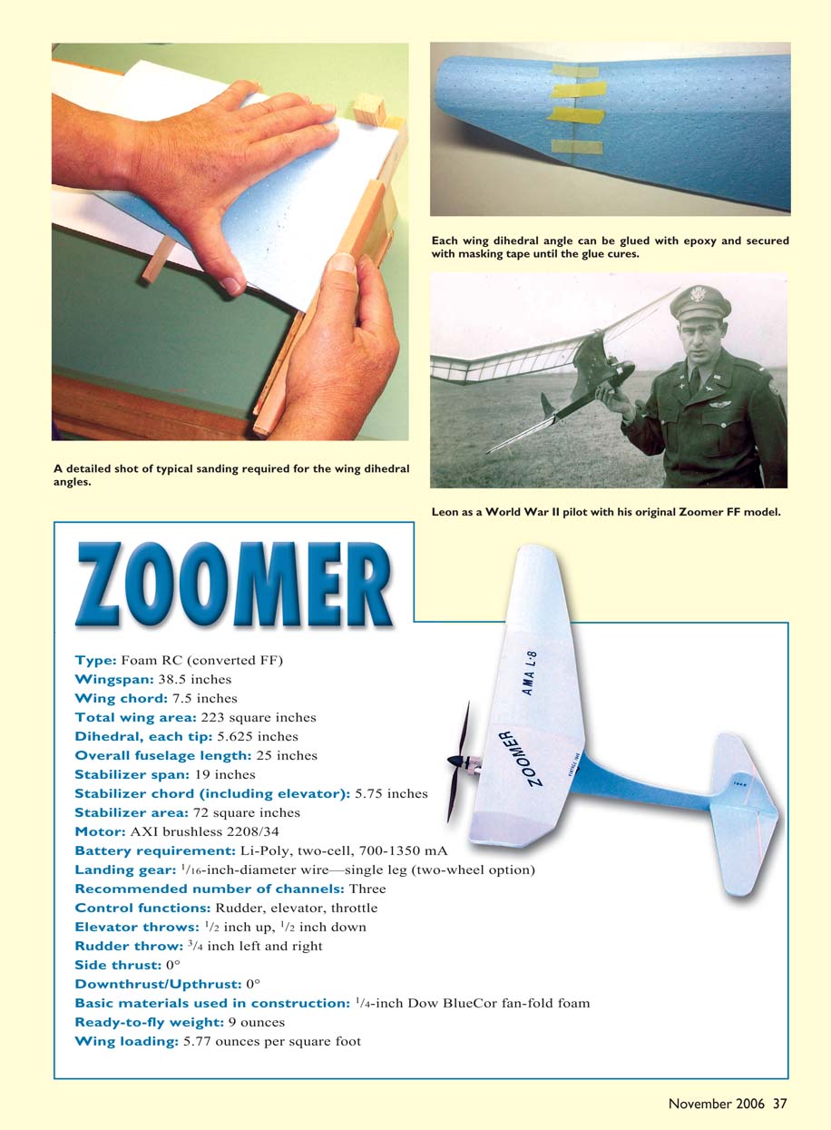
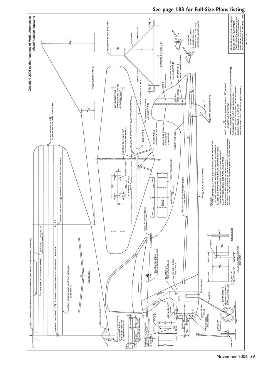
The Zoomer’s fuselage structure was radical for its time, following my earlier Banshee design: simple, light, strong, and easy to assemble and repair. It allowed smooth, flowing lines and easy covering. The original design incorporated a single-wheel landing gear (with an optional two-wheel layout) and two small subrudders on the horizontal stabilizer for quick takeoffs and smooth landings with minimum drag. Quick access to ignition units and batteries was provided by a simple hatch on the fuselage bottom, and the motor was faired into the fuselage with a spinner to smooth airflow.
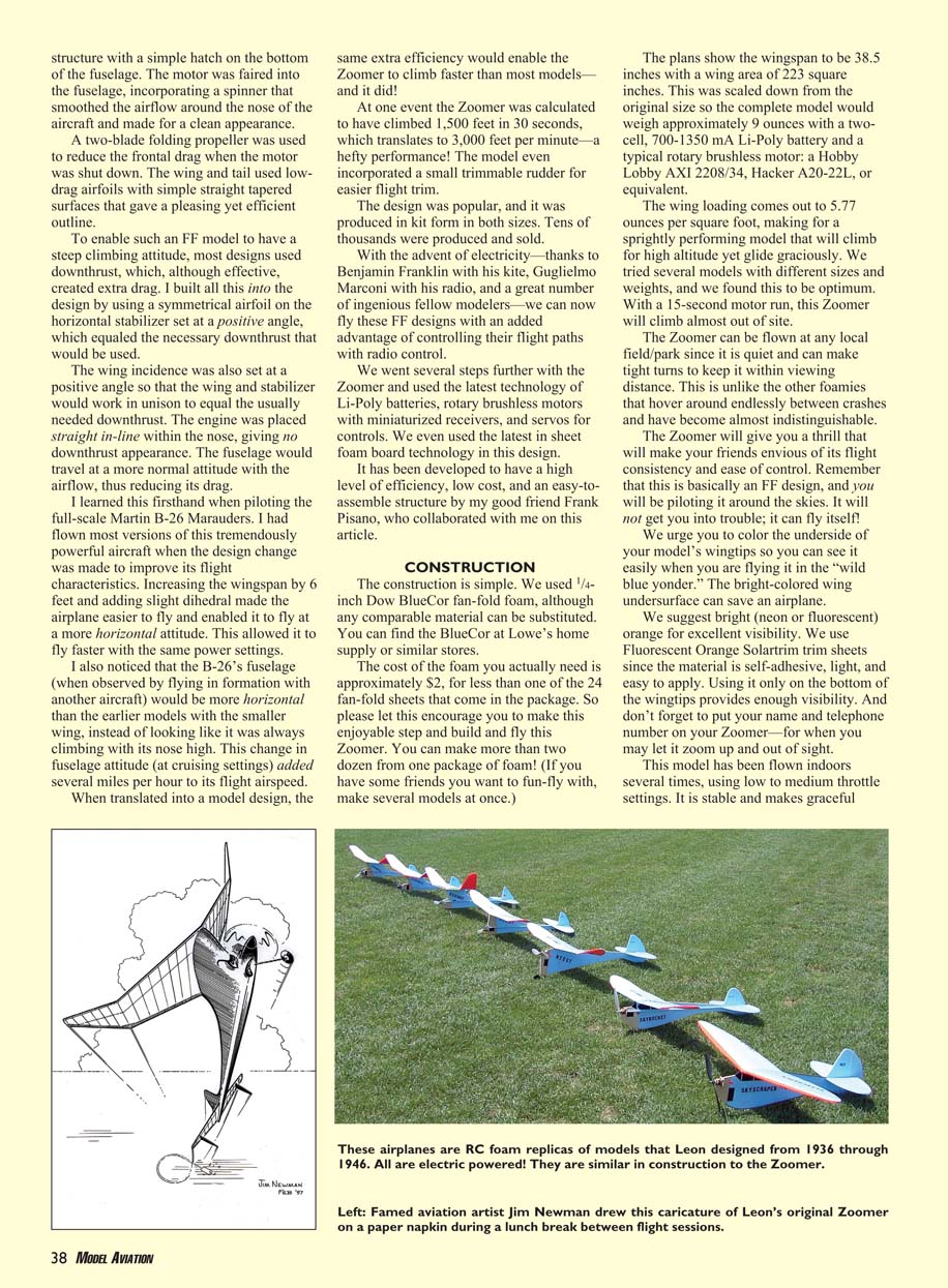
With the advent of electric power and modern miniaturized radio equipment, we updated the Zoomer using Li-Poly batteries, rotary brushless motors, and small receivers and servos. Frank Pisano collaborated on this development, yielding a high-efficiency, low-cost, and easy-to-assemble RC foam version.
SPECIFICATIONS
- Type: Foam RC (converted from FF)
- Wingspan: 38.5 in
- Wing chord: 7.5 in
- Total wing area: 223 sq in
- Dihedral, each tip: 5.625 in
- Overall fuselage length: 25 in
- Stabilizer span: 19 in
- Stabilizer chord (including elevator): 5.75 in
- Stabilizer area: 72 sq in
- Motor (original recommended): AXI brushless 2208/34
- Battery requirement: Li-Poly, 2S (2-cell), 700–1350 mAh
- Landing gear: 1/16 in diameter wire—single leg (optional two-wheel)
- Recommended number of channels: 3
- Control functions: Rudder, elevator, throttle
- Elevator throws: 1/2 in up, 1/2 in down
- Rudder throw: 3/4 in left and right
- Side thrust: 0°
- Downthrust/upthrust: 0° (trim is provided by stabilizer incidence)
- Basic construction material: 1/4 in Dow BlueCor fan-fold foam (or comparable sheet foam board)
- Ready-to-fly weight: ~9 oz
- Wing loading: 5.77 oz/sq ft
DESIGN FEATURES
- Symmetrical airfoil on the horizontal stabilizer set at a positive angle to provide the equivalent of downthrust without adding engine-mounted downthrust (reduces drag).
- Positive wing incidence so wing and stabilizer work together for the intended climb attitude; engine is mounted straight in-line in the nose.
- Two-blade folding propeller recommended to reduce frontal drag when motor is off.
- Low-drag airfoils with straight-tapered surfaces for efficient flight and pleasant appearance.
- Removable wing held with rubber bands for transportation and damage resistance.
- Small trimmable rudder for easier trim adjustment.
- Optional motor beam to accept lower-cost brushed motors with small weight penalty.
CONSTRUCTION
Materials and tools
- 1/4 in Dow BlueCor fan-fold foam (or similar)
- Knife (X-Acto #11 blade recommended)
- Sandpaper (320-grit recommended)
- Sanding block
- Clear packing tape (for hinges)
- Cyanoacrylate (CA) and 5-minute epoxy
- Masking tape
- 1/32, 1/16, 1/8 in plywood (for fittings)
- 1/16 x 1/4 in basswood or hard balsa strips (stiffeners)
- 1/16 in diameter wire (landing gear)
- 1/8 in inside-diameter brass or aluminum tubing (short piece for leading edge reinforcement)
- Two skewers (embedded into leading edge for strength)
- Du-Bro Hook & Loop Mounting Material and Double-Sided Tape (optional) or equivalent mounting methods
Cost note: The foam used for one Zoomer is typically only a small fraction of a fan-fold pack; a single pack can yield many models.
Wing shaping and airfoil
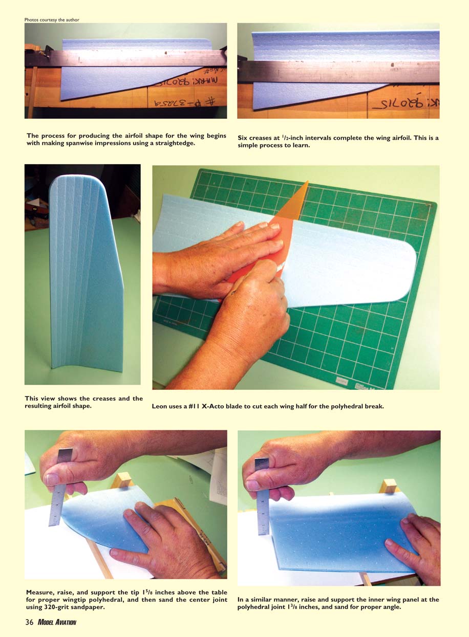
- The wing airfoil is produced by making spanwise impressions with a straightedge and creasing the foam in six 1/2 in increments across the panel to form the airfoil shape. This method produces an efficient, light, and strong wing.
- Cut each wing half for the polyhedral break using a sharp blade. Use a #11 X-Acto blade for clean cuts.
- For wingtip polyhedral: measure, raise, and support the tip 1-5/8 in above the table for proper wingtip polyhedral; sand the center joint with 320-grit sandpaper.
- Raise and support the inner wing panel at the polyhedral joint 1-3/8 in and sand for the proper angle.
- Glue each dihedral joint with epoxy and secure with masking tape until cured.
- A short piece of 1/8 in inside-diameter brass (or aluminum) tubing, with two skewers embedded and epoxied into the leading edge, adds considerable strength and resistance to scrapes and rough handling. Four keys locate wing position for consistent settings.
Control surfaces and hinges
- Bevel 1/8 in from the bottom edges of the horizontal stabilizer and one side of the vertical fin.
- Add basswood stiffeners to each control surface with a light coat of epoxy.
- Use clear packing tape for hinges on both sides of movable surfaces:
- Place stabilizer/elevator flat on the bench with the bevel gap on the bottom.
- Insert a 1/32 in wire or dowel between surfaces to create a 1/32 in gap and press hinge tape over both surfaces.
- Remove the wire/dowel, fold surfaces the opposite way, and apply a second piece of tape to complete the hinge.
- Repeat the same process for vertical surfaces before gluing the horizontal surfaces in place.
Assembly and fittings
- Cut all parts to shape and assemble the landing-gear socket first using CA.
- Use epoxy sparingly to minimize weight; mask and clamp with tape while epoxy cures.
- Locate and glue the motor mount, servos, receiver, controller, and battery per the plans. All incidence and motor-thrust settings are built into the structure.
- Use Du-Bro or equivalent light mounting materials (hook-and-loop, double-sided tape) to secure the receiver, ESC, and battery.
- Use micro control horns and micro pushrod systems to connect to small servos. Polk's Seeker 6 or similar light-weight receivers are recommended for their range and light weight.
- The balance point should be approximately 50% back from the wing leading edge (not critical but a good starting point). Bench-test and trim before flight.
ELECTRONICS, POWER, AND PROPS
- Original recommended power: Hobby Lobby AXI 2208/34 brushless motor with a Jeti 8A speed controller (or Castle Creations Phoenix-10) and an APC 10 x 4.7 Slow Flyer prop for excellent performance.
- Alternative power: Hacker A20-22L or equivalent brushless motors.
- Lower-cost option: GWS 350C-C geared brushed motor with a Castle Creations Pixie-20 or similar controller and the same APC 10 x 4.7 prop. Performance is comparable with a slight weight penalty for the brushed option.
- Battery: 2S Li-Poly 700–1350 mAh.
- Prop: Two-blade folding recommended to reduce drag on glide.
FLIGHT CHARACTERISTICS AND TRIM
- The Zoomer is designed to "zoom" in a steep climb and then transition into a gentle flat glide.
- With the recommended power and a 15-second motor run, the Zoomer will climb very high: at one event it was calculated to climb 1,500 ft in 30 seconds (≈3,000 ft/min).
- Control input under power should be gentle; the design has inherent stability and will often fly itself.
- The aircraft is not designed for aerobatics (loops or rolls). Enjoy its spectacular climb and graceful glide landings.
- Flights of 15–45 minutes are normal; longer flights possible when there is lift (e.g., ridge or thermal).
- Mark the underside of the wingtips with a bright color (neon/fluorescent orange recommended) for visibility. Self-adhesive Solartrim or similar works well. Put your name and phone number on the model in case it flies out of sight.
TESTING AND FINAL NOTES
- Bench-test all electronics and verify control surface throws: 3/4 in rudder, 1/2 in elevator.
- Verify center of gravity and control directions before first flight.
- Avoid severe gusts due to the light weight of the model.
- The removable wing and simple construction make repair and transport easy. Plans include parts, fittings, and dimensions.
- The plans also show a simple motor-beam option for using alternative motors.
Keep ’em flying!
Leon Shulman [email protected]
Transcribed from original scans by AI. Minor OCR errors may remain.

