
IT pretty Shareen lsTedsbetterhalfWCdOflt Uknow what makes Imitation thing beauty its own right 59-inch ship profile variation true profile beginning just forward cockpit Desinn te 2 Editors Note order reenforce read ers impressions authors discussion design development borrowed photos intended next months construction feature plans will repeatedso sure keep issue reference Both installments include vast amount priceless information relating photos uur necessarily generalized captions instance justice author knowledgable stunt flier THE Imitation designed flying testbed explore soundness num ber aerodynamic philosophies experimenting through Citation series competition stunt air craft addition intended used discriminating stunt pilot in-depth exploration aerody namic philosophies being evolved through authors Citation series aircraft Article plans Imitation appear next month Ted Fancher test suitability stunt purposes variety currently available very powerful Schnuerle-ported 40 engines Citation although has enviable contest record including third second last two National Championships does have couple significant shortcomings felt corrected before investing time effort new competition airplane First foremost too much thorough bred although capable outstanding performance entirely too critical trim adjustments weather conditions necessary spend con siderable time before contest trimming adjusting peculiarities contest site instance before qualifying 78 Lake Charles Nats tear September 1979 39 out almost full ounce nose weight order regain same degree crispness corners had cool heavy air Northern California addition necessary explore whole series props find would allow crisp maneuvers result excessive air speeds single perplexing prob lem however Citations inability come out corner hard flat time altogether too sensitive handle adjustment center gravity location pM has literally nursed around cor ners occasional bobble avoided Because need resolve problems decided design easily built test ship would allow investi gate possible solutions meaningful such design would have combine ease construction truly competitive planform would nearly possi ble display characteristics state art competition stunt plane Such combination would have include An inverted engine appropriately lo cated fuel system ie directly behind engine adjustable vertical allow trimming consistent engine runs addition should possible easily interchange engines explore potential replacements venerable ST 46 planform je wing span wing area mo ment arms horizontal stab elevator area aspect ratios etc would have identical competition plane same size although would easy matter build simple profile significantly lighter competition ship temp tation avoided lighter wing loading would make results tests meaningless translation heavier ship compliance basic para meters Imitation came off building board sporting semi full fuselage front end supporting Kraft-Hayes 1CM40 engine mount easily removable accommodate variety engines cut out incorporated nose allow fuel tank properly located allowance made space shim tank either up down Aerodynamically Imitation features 59-in wing span 631 sq area results aspect ratio 55 unfamiliar term aspect ratio mathematically defined length wing span squared divided area constant chord straight tapered wings wing area divided average chord comparatively long tail employed along large horizontal stab elevator 140 sq 222% wing area No attempt made keep weight down result Imitation came out weighing 50 53 ounces de 40 Model Aviation nice touch lathe metal plate attaches 4 flathead screws over landing gear wire mounts normal fashion simple block assemblyControl Specialties item right wing tip ShOwing nylon bolt variable weight box flap pin Mul tiple segment flaps allowed experimentation four different lengths high-lift device evaluation merits demerits Teds findings given text Teds handle adjustable both lines picture makes clear manufacturers re minder notto fly nearoverhead power lines excellent safety remindersome require 59 0123456 w-J-w-j-J pending weight engine translates wing loading 114 121 oz/sqftactually slightly heavy competitive range Citation inw stance has wing loading 110 ozIsqft addition basic requirements now mandatory adjustable fea tures would have included order TED FANCHERS IMITATION rAD achieve optimum flight trim personal approach such things adjustable line guides tip weight tail weight control ratios forth detailed plans T C/2 CI MGC CL MGC 4CI L KCI FIGURE m LIFT VERSUS ANGLE OF ATTACK AND AIRFOIL CAMBER RELATIVE~ LOW LIFT AIRFLOW BOOY ANGLE -0 FLAP DEFLECTION RFOIL UNCAMBERED NON-LIFTING SECTION ANGLE OF ATTACK-OF FIGURE II LOCATING ThE MEAN DEOMETRIC CHORD I LAYOUT THE TOP VIEW OF THE WING 2 EXTEND ThE ROOT CHORD IN EITHER DIRECTION FOR DISTANCE EQUAL IN LENGTH TO THE TIP CHORD 3 EXTEND THE TIPCHORD THE OPPOSITE DIRECTION FOR QSTANCE EQUAL IN LENGTh TO THE ROOT CHORD 4 CONNECT THE ENDS OF THE EXTENSIONS MADE IN STEPS 2 AND 3 5 CONNECT MID POINTS OF ROOT AND TIP CHORDS THE MGC ISA UNE RALLEL TO THE ROOT CHORD LOCATED AT THE LOCUS OF THE LINES DRAWN IN STEPS 4 AND S ASSUMED CENTER OF LIFT IS NOW LOCATED 1/3 OF THE I-IORO LENGTH AFT OF THE LEADING EDGE AT THE MGC RIV RE AIRFLOWMODERATE LIFTAIRFLOW BODY ANGLE LAP DEFLECTION AIRFOIL-UNCAMBERED NON-LIFTING SECTION ANGLE OFATTACI- 10 DERIVATION OF CONTROL EFFECTIVENESS RATlOS ERs TAlLER AXL WING VOL FLAP ER A2X L2 WING VOL AXLA2XLz TOTALCONTROLERSWING VOL WHERE TAIL AREA A2 FLAP AREA CL WING TO CL TAIL IN INCHES CL WINGTO FLAPHINGELIN IN INCHES C A1 WING VOL MGC X WING AREA FIGURE ] BASIC AIRFOIL TERMINOLOGY NOTES ON SYMMETRICAL AIRFOILS CHORD AND CAMBER LINES COINCIDE ThICKNESS AND ITS LOCATION ARE EXPRESSED AS PERCENrAGE OF THE CHORD IE IB% THICK AT 25% OF THE CHORD LOCATION h-oF IAAXI THCKILSS ICAMBER ILINETRAILING EDGE MAX THICKNESS ----LEADING EDGE LEADINGCHORD LINE EDGE RADUS LEGEND CHORD LINE CAMBER LINEcC ANGLE OF ATTACKhI IS HIGH LIFT BODY ANGLE LAP DEFLECTION IRFOIL-CAMBERED LIFTING SECTION ANGLE OF ATTACK-IS September 1979 41 pictures accompanying article construction article follows next month generally straightforward unusual items will addressed completely appropriate point couple innovations quite unusual occasioned desire evaluate effects flight characteristics ship obvious multiple segment flaps allow experimenting four different lengths high-lift device evalua tion merits demerits very interesting will expand findings bit second unusual adjustment firewall spacers allow move engines forward aft thus varying nose moment arm has opin ion some time length nose moment significant terms flight trim Rather spend time let just state nothing have learned result ability move nose moment much has given reason change opinion regard could tell no difference flight characteristics result longer shorter nose provided center gravity remained same location Suffice say am happy whatever nose length results least need additional weight bring airplane proper flight trim Try spacers like just remember adjust CG remains constant throughout ex periments Other less obvious innovations include use very thick horizontal stab elevator employing Warren Truss con struction rigidity Du-Bro Ball Links control linkages homemade circular 3 bellcrank have detailed plans have access machinist nice feature standard Sig Top Flite nylon bellcrank would yeoman service slightly increased control forces handle Once design goals established next step translate paper usual approach designing original stunt ship lay out profile would hopefully provide flight charac teristics desired after laying out essentials would wrap results gossamer personal vision table shown Fig developed Bill Fitzgerald myself over past five years Its purpose display mathe matically approximately 40 parameters felt significant affecting manner stunt ship flies Initially used table collect com parative data several proven designs familiar primary emphasis factors establish rapid pitch change rate turn stabil ity compilation along certain amount basic aerodynamics familiar eventually allowed us develop mathematical concept what potentially outstanding stunt ship should look likeby numbers items table self explanatory few parameters may unfamiliar Taper ratio ratio tip chord root chord ie wing 75-in tip chord 10-in root 42 Model Aviation Adjustable leadouts may mystify novices allow corrections wide variety trim problems fine tune airplane fly cor rectly Teds neat arrangement two views multiple segment fisps afford impres,., .un uu 561 up variety conTigurations show determination during test flying condition preferred pilot give him precisely ins cnaracteristics during various maneuvers seeks paper appeals designer try find place locate mundane essentials such wing tail engine tank wheels etc decided use least 10% scientific approach deciding what aerodynamic layouts chord would have taper ratio 75% MGC Mean Geometric Chord graphically derived station along span closely approximates Mean Aerodynamic Chord See Fig II point results aerodynamic forces may assumed concentrated practical purposes simple tapered wing planforms Mean Aerodynamic Chord MGC may considered identical design purposes have arbitrarily designated point 33% aft leading edge MGC Center Lift arbitrary point used datum reference point design parameters followprimarily dealing moment arms may well say now though may con sidered heresy classic measure moment arms ie back prop wing leading edge crack crack flaps elevators practically no value Because takes no cognizance different planforms top view wing tail shape relationships aspect ratios can seen instance 15-in tail moment 600 sq airplane 54-in span bears little resemblance 15-in tail moment 600 sq airplane 65in wing swept back 200 merit such comparisons must based common reference design discussion purposes arbitrary ref erence should established have chosen use point titled Center Lift table Harkening back comments regard ing adjustable nose length note have result test bothered measurement nose moment just dont think its significant Argue love Volume wing mathematical product wing area multiplied Mean Geometric Chord used later calculation regarding stabillty control effectiveness using wing volume force calculations rather just wing area get measure effectiveness aspect ratio determining control re sponse As aspect ratios decrease ie MGC becomes larger wing volume becomes larger effectiveness tail surfaces both control stability decreases later will notice area covering flaps becomes somewhat cluttered due use four different flap sizes Rather try totally digest numbers suggest read conclusions experiment later article both flap tail sections table have entry flap/tail volume might appropriately called flap/tail percentages reflect comparative size flaps tail comparison wing three Effectiveness Ratios Flap Tail Total Control developments work solely compari son plane another See figure IV have no mathematical basis valid ity other purpose What tempted illustrate potential forces developed tail flaps affect flight path wing tail virtue lift develops multiplied its September 1979 43 Above We wont comment tne coupling flaps elevators illustrated photo cause author goes deeply other matters both article next months construction feature point interest fairlead eliminate pushrod deflection Below flap horn set up allow throw adjustment short/long pushrods pushrods threaded use Du-Bro ball links -oz Sullivan nylon oval slant tank taken out show contours cutout mounting Arrangement used plans published distance datum capable applying X amount force achieve change angle attack flaps virtue same two factors able apply Y amount leverage affect angle attack however opposite direction Both forces acting wing has certain amount reluctance change direction based pri marily its size shape Therefore subtracting restraining force flaps force tail relating result wing volume able derive number roughly approxi mates ability given airplane change directions As number gets larger ability airplane corner briskly increases As will note later discussion regarding variable length flap experiments validity ap proachif mathematical soundness formulais totally supported dislike Im sure designer tells did something certain way very good reason doesnt want bore technicalities very fair him pass cloak ignorance readers Therefore Im going run down conception what stunter should look like general least cursory explanation feel particu lar characteristic employed Imita tion important disagree thats great Its about time stunt world some controversy over something sides judging First feel should using higher aspect ratios stunt ships Higher aspect ratios result significantly lower induced drag high lift-drag situations such square corner Rapid drag build up causes speed decay demands greater horsepower engine Reduce drag build-up corners need automatic four cycle/two cycle engine run becomes less demanding Since induced drag comes combination tip vortices miniature horizontal tornadoes formed tips high-pressure air bottom wing being drawn around tip low-pressure area top wing down-wash tend ency high velocity air particles upper surface wing continue downward beyond trailing edge can reduced moving tips further apart good argnment raked style wing tips versus flat plate types reducing length chord wing given area ie higher aspect ratios some negative results higher aspect ratios Maintaining struc tural integrity longer wing difficult care must taken avoid warps effects pronounced terms performance lowered induced drag results aircraft has increased sensitivity power prop changes have found necessary use large diameter lower-than-normal pitch props maintain proper lap times control increased tendency accelerate consecutive maneuvers Zinger 12X5s 1 2X4s seem ideal resulting lap times 55 57 seconds per lap nicely controlled airspeed maneuvers 62-foot lines have also doing some testing Bobby No 1 Hunts three-bladed Rev-Ups shows some promise Secondly tails should significantly longer both stability turn perfor mance effect stability relatively easy perceive dont believe open serious debate other hand large school thought argue merits shorter tails because get kick closer CG throw plane around corner understand concept error necessary understand concept moment arm effect has pitch change angle attack lift produced resultant body angle Assume entering first corner inside square loop What judges looking simplest terms 90degree change flight path concept change body angle result air pushing against deflected elevator 44 Model Aviation could almost write book about things evident discerning stunt pilots eye hinging jam nut clevis easily accessible compartment flexibility use weights Deep cheek blocks thatcontourthe basic profile afford opportunityto neatly submerge exposed tank mount carbon/glass Kraft-Hayes item familiar RC people Firewall spacers allow up movement Fancher regards essential CG remain specified causing aircraft rotate about center gravity simply true chronological order what fact takes place following must understood tail func dons deflecting air rather producing lift same way lifting surface ie through difference pres sure between top bottom airfoil lift thus produced multiplied its distance aircrafts center gravity product lift force ap plied multiplied forces distance center gravity moment arm Increase either resultant force increases force thus applied causes aircraft pitch up resulting increased angle attack turn results increased lift wing Assuming sufficient thrust overcome induced drag comes increased lift can seen aircraft will continue increase angle attack long force continues applied tail rate proportional degree force being applied until such time force removed plane continues along newly achieved flight path Since air craft has inherent desire remain motion along given path until displaced outside force obvious greater force applied rapid will resulting change flight path Therefore longer tail moments will result tighter turns less lift drag shorter tails Thirdly aircraft size increases find control inputs necessary deflect larger control surfaces against slipstream becoming greater well compara tively small man such myseW increased requirements muscle center circle become substantial especially light need hundreds practice flights year problem can attacked both aerodynamically mechanically Aerodynamically forces can reduced both reducing proportion surface deflected ie smaller elevators flaps keeping chord deflected surfaces short reason able easily demonstrate latter phe nomenon try deflecting rectangular object such piece wood approxi mately four times long wide 4 1 aspect ratio both lengthwise widthwise against slipstream outside car window 55 mph will notice consi derably resistance attempt deflect surface lengthwise demonstrates significantly reduced con trol leverage required high aspect ratio control surfaces Because fact such long narrow lift device efficient creates less drag short fat ones feel flaps should limited between 15 20% wing chord given station wing Imitation results flaps 17% chord stations proponents large elevators probably questioning sanity suggest smaller ones Again important remember force causes pitch change comes lift produced entire tail solely amount surface deflecting slip stream Therefore what looking efficient lift-producing surface Prob ably efficient tail would have elevator comprised approximately 25% total tail surfacesomething like Flite Streak everyone knows will outmaneuver conventionaltailed Ringmaster hands down however some compromise necessary terms drag stability makes larger optimum elevators result aircraft stable maneuvering Since moving cen ter drag aft stabilizing its effect since certain amount drag comes hand hand lift tail produces maneuver apparent sacrifice little drag can build airplane controllable maneuver ing has less tendency over shoot headings same reason thicker tail employed along lower aspect ratio Such tail wont efficient terms maximum rate turn will come close net effect will enhance overall flyability air plane As result compromises Imitation has tail totals 140 sq 55% stabilizer 45% eleva tor aspect ratio tail 45 1 Mechanically control forces can re duced achieving increased mechanical advantage over aerodynamic resistance Continued page 114 September1979 45 Ted makes no comment stooge readers have asked make onethet include explanatory picture Stooge anchored ground string pulls release pin Voile1 Some variety 40-size engines used during thedifferent firewall spacers required Metal tank appears picture does muffler pressure arrangement fYOYflO PROPELLERS Madeof polyester boil orcolor Go GRISH propeller True helical pitch airfoil win-power 2 Blade Tractor 53each 54535430d 636435d 74767850 84868865d 949697 9810-410685dneeds 114116118 Si 124125126$150 2 Blade Pasher 543 54-4636435 86854 96106Si 3 Blade Tractor 53 63 64504 3 Blade Pasher 63s043 mmBlade Metallic Aluminum color Tractor ifiB Si 86885125 96061045150 Pusher06 $150 Sizes pitches GRISI4 LARGE WOOD PROPELLERS HARDWOOD too hard minimizes chance costly plane engine damage True pitch airfoil fully finished balanced ready coating 318 BOREALL SIZES IN18 $7 68&lOPITcH 20 8 22 10 24 13 REYCKASIR little piece electronic wizardry quickly easiiy reverses direction servo travel plugged between receiver servo will work positive pulse servos e four wire Connectors NOT furnished Available unassembled kit form assembled tested 14K104Ace Servo Reverser kit $795 14K104CAce Servo Reverser assy $1150 details send $1 latest catalog Add $50 1st class return $1 hand ling direct orders 816 584-7121 IAE E/IrnJ Box ShE HIGGINSVILLE MO 64037 NEW ERA PUBLICATION CUSTOM TUNED ENGINESAEROBATIC AIRPLANES BY PORT C MORRISON COMPETITION ACCESSORIES4U PAGES I 52 PHOTOS Cox 049L051 SpecialistsU OE1AILEO DRAWINGS brochure send 15c stamp toOnly 6395 PLUS SOft POSTAGE Kuslom Kraftsmanship BrochureCATALOGS 3100 REPLA-TECH Box 2699 Laguna Hills CA 92653INTERNATIONAL icc 714 830-51624U500 MC KENZIE HWY VEGA OREGON 9745E several hours Texas covered monstrous high pressure system day surely some drift expected point turned TV discovered looking weather balloon released morning Palas tine TX National Science Foundation jumbo 450 feet diameter containing 40 million cu ft helium floating 23 miles overhead am still amazed unaided visual identifi cation object 120000 feet Apparently others switchboards Dallas went wild after sundown reflected sunlight produced pinkish cast side polyethylene balloon leading thousands UFO reports Dee B Mathews 506 S Walnu Greensburg KS 67054 writing advertisers mention read about Model Aviation mitation/Fancher continued page 45 deflection Simply stated means longer control horns bigger bellcrank Imitation uses homemade 3 circular bellcrank maintains its full 1 fulcrum entire range control movement pushrod exits bellcrank 09 bellcrank axis attached DuBro Ball Link flap horn inch flap hinge line flap elevator pushrod located 075 inches respective hinge lines classic one-to-one flap elevator ratio conven tional horn employed elevator allow use elevator slop necessary now appears ball links could have used throughout long tail moment large surface area tail have proven provide stability could hope handle provides finishing touch control system modified Custom Master Flight Handle designed Bob Baron produced Gene Martine Custom Master Products 5424 Oliver Street S Jacksonville FL 32211 Before leaving subject control surfaces lets talk bit about variable span flaps effect flight characteristics Imitation First lets once rid ourselves desire think flaps separate distinct wing Wing flaps simply part wing happen attached such way may moved up down about hinge line doing make substantial changes characteristics airfoil Reference Figure III changes significantly affect amount lift wing given area capable producing classic symmetrical stunt airfoil often referred non-lifting section inas much its top bottom surfaces mirror images result camber line line drawn equidistant top bottom surface straight line Theoretically such section zero angle attack would produce no lift due being no differential velocityand fore pressure above below wing Now hinge aft 15 20% wing surface deflect downward will have altered number things First have instantly changed uncambered non-lifting aiifoil cambered lifting Also since measure airfoils angle attack defined angle between relative wind line between leading edge trailing edge chord line have concurrently increased angle attack two items acting concert have made quantum increase amount lift produced same airfoil its natural symmetrical state apparent amount flap area important factor determin ing amount additional lift produced Rather percentage total wing span equipped high lift device significant other words wing has 15% its total area flap along its full span will produce signifi cantly lift same wing 15% its total area flap concen trated say s span So far well good Weve seen can apparently get something nothing almost instantaneously just bending back wing however small fly ointment buzzes around fact center lift almost exception located some what aft center gravity Addition ally center lift will move further aft deflection flaps concur rent increases lift angle attack As result divergent location 114 Model Aviation styles AT YOUR DEALER RIGHT HAND TRACTOR NEW SIZE IN B & 10 PITCH 26 $16 GRISH BROS ST JOHN INDIANA 46373 * SEND STAMPED SELF ADDRESSED ENVELOPE FOR COMPLETE STATISTICS AND FULL SIZE DRAWINGS DUBRO PRODUCTS INCORPORATED ILL 6CO84 centers lift gravity moment produced between two whenever either increased case classic stunt configuration center lift aft force manifests itself negative pitching moment wants pitch nose direction opposite desired change pitching moment adversely affects ability make rapid changes attitude therefore best interests minimize its effects seriously search elusive rule-book corner Since pitching moment again product lift times its distance center gravity minimizing its effect must come through reduction other Any reduction lift would have come through decrease flap size since need lift can generate its reduction viable solution pitching moment dilemma decrease arm achievable variety ways Higher aspect ratios inherently have less distance between CL CO Smaller chord flaps also result less rearward movement CL deflection third possible method shortening arm move CL forward attempt accomplish high point airfoil Imitation placed 22% chord full span full 8% further forward Citations 30% Finally classic method merely mov ing CO aft always available through addition tail weight design such Imitation its high stability coefficient ie large tail long arm much amenable such solution can withstand much furth aft CG becoming unstable addi tion large tail long moment arm provide leverage necessary overcome adverse pitching moment fore retain adequate turn potential full span flaps opinion last two itemsmoving C/L forward ability move CG aft still retain adequate stabilityare pri marily responsible improvement Imitations ability come out corners hard flat compared Citation silver lining pitching moment cloud however negativeor purposes opposing-pitching mo mentis stabilizing its effect Imagine briskly rotating bicycle wheel no resistance trying stop precisely predetermined point Now mentally repeat same exercise light moderate brake pressure resisting efforts imagine much easier would stop precisely pitching moment wing acts same manner resist stabilize efforts change its attitude against its wishes Flight tests Imitation varying flap sizes seem back up foregoing theories initially flown innermost sections flap operable flights configuration spectacu lar came corners 60% span flapped total 11% total wing area movable pitching moment minimal huge lever age tail plane could literally leap through corners Unfortunately round maneuvers suffered nearly uncontrollable tendency wander Minor control inputs would cause noticeable pitch changes mani fested visible flat spots rounds As increasing amounts flap made oper able extremes explosive corner marginal tracking began moderate Now corners although still impressively tight became much controllable pre cise exits easier As pitching moment additional flap increased plane became much easier fly through round maneuvers tracking improved remarkably experiment flaps made tempting build competition airplane same feature windy weather G forces build up consecutive maneuvers would tempting able fix some flap reduce adverse pitching moment hard corners thus reduce eliminate loss corner normally associated flying wind think though temptation should avoided because its adverse effect round maneuvers fact would never really come know plane intimately Although learned great deal experiment still dont feel confident could say much flap ideal will cautiously generalize little tco much probably better too September1979 115 ENGINE HAS GOT IT FUEL TUBING CLEAR NEOPRENE SUPER BLUE SILICONE FUEL AVAILABIE OFF ThE ROLL OR PACIAGED IN 2 LENGTHS CATPKG NOFUEL TUBINGPRICE 2182 FT CLEAR VINYL-SM.30 2192 FT CLEAR VINYL-MED.40 2202 FT CLEAR VINYL-LG.50 2212 FT SILICONE-SM.90 2222 FT SILICONE-MED$110 2232 FT SILICONE-LG$150 2242 FT NEOPRENE-SM.60 2252 FT NEOPRENE-MED.80 2262 FT NEOPRENE-LG.90 ir SLOW POWERFUL FLIGHT IS ACHIEVED WITH THIS UNIT MAKING YOUR AIRCRAFT LOOK AND SOUND REALISTIC RPMS RANGING FROM 600-5000 DEPENDING ON ENGINE AND PROPQOt PItOo r SWING 18 20 22 AND 24 PROPS WITH 8 OR 10 PITCH WITH YOUR 60 ENGINE NNOUNCINGThe New Instant-Dry f Adhesive Process K Ffl ToSheetFoam Wing Cores new product Corefilm replaces using white glue epoxy contact cement sheeting foam wing cores Corefilm rough thin lightweight mylar tape has ooated both sides contact adhesive Corefilm ready instant use After oovering wing core 11/2 strips corefilm remove paper backing set plywood balsa sheeting material place press foam core bond instant Corefilm flight tested gliders power ships tough mylar film provides strapping tape effect both top bottom has proven desirable superior quality Corefilm comes 1% wide 36 yard rolls roll will cover over 1900 sq 13 sq dealer direct Write brochure complete line BILL 19216 Calvert Street Reseda CA213/344-6391 Quiet Power -Tatone Makes new super quiet K&B 40 R/C muffler requires machined fit exhaust stack cover Easy no exhaust plugs fittings adaptors Muffler exposed holes Just bolt on.thats itl Will reduce noise 10 12 decibels little no loss rpms Noise cancelled interposing sound waves eRadi cal free flow expansion chamber angled blow exhaust away fuselage attach provision pressure fitting Also available ENYA 29 35 40 45 OS MAX 30 35 40 SUPER TIGRE 021 35 46 Add $100 extra above engines specify type Mounting strap screw included $1295 No 306 Add $125 postage handling CA residents add 6% tax Dealer inquiries 1931 Gee Bee Super Spo1Scale General Arrange-I - ment Drawing Catalog 25c W T Bill Given MODERNISTIC MODELS PO BOX 6974 ALBUQ NM 87197 little higilpoints design philosophy resulted Imitation say plane success would unfair understatement facts respects best flying plane have flown terms tight precise corners has few peers experimental features tested Imitation successful results now being incorporated new competition ship Excitation Because relative ease construc tion Imitation should reasonable project builder few profiles under belt Due ts outstanding flying capabilities perfect selection contest machine beginners GET ORGANIZED set 4 st.d ties 00kM Osr 4 years yes taole II eragazeres 4 MAO FILES $495 Seod 5496 pMe $1 00 postage wd taneag DaM iwnuemma PO Box 3M-K DOVER NH 00000 advanced fliers Any builder desires far better average plane practice impressive Sunday barnstorming ought take close look Continued Suggested Reading Fundamentals Aircraft FlightFred erick K Teichmann Hayden Book Co Inc Rochelle Park NJ Aerodynamics forNavalA viatorsIssued Office Chief Naval Opera tions Aviation Training Division Primar ily Chapter Pages 1 through 95 FLY SAFELY CL Speed/Hempel continued tram page 47 eral Speed supplies Rossi engine parts John Newton 2154 Los Padres Drive Rowland Heights CA 91748 lane parts Chuck Schuette-design asymmetric sidewinder Questions concerning article FAI Speed general may addressed Charles Lieber 725 Signal Light Rd Moorestown NJ 08057 Gene Hempel 301 North Yale Dr GarlantL TX 77459 CL Scale/Gretz continued page 48 authentically contoured spinners available parts castof gray epoxy resin ready-to-paint no priming extensive sanding required samples saw ap peared very accurately researched duplicated displayed excellent workmanship Also available firm hand-carved laminated wood scale props suitable WWl vintage kits market also come ready-to-finish include metal hub plates scratch-builders Keeler will make custom props either cast resin wood providing can furnish adequate scale documenta don should include diameter fullsize prop photos drawings possible materials will returned upon completion prop RingAroundthe. Cockpitl oldest tricks scale modeling book using fuel line tubing simulate padded edging normally found around rim open cockpits vintage full-scale aircraft com monly referred cockpit coaming building CL Sport Scale PT-i 9 became reacquainted familiar technique jotted down few notes may interest coaming around cockpits actual full-size PT-19 duplicating made padded black leather type typical older open cockpit aircraft may find some homebuilt types today will have foam rubber edging case need find brand tubing has right diameter wall thickness give correct degree size roundness found some W ID IA OD black neoprene rubber tubing formerly marketed VECO looked just right 10 feet away 1/6th scale modeL After finish complete used sharp #11 X-acto knife cut cockpit openings final shapeThen flat black anti-glare panel painted dry cut piece tubing cockpit slightly longer figure actually needed Use sharp blade again cut through tubing lengthwise along side can opened up slipped over cockpit edge trial fit tubing model first time glue Start end very carefully go way around making certain tubing isflrinly pushed up against balsa edge before cutting itto final length youre completely satisfied will fit desired take off mix up batch slow drying overnight epoxy glue Use piece wire work epoxy inside tubing Slip tubing back place model use plenty pins secure balsa cockpit until glue dries tubing using necessary push pins firmly withdraw just slightly holding tubing back fingers avoid leaving permanent dimple tubing after epoxy 116 Model Aviation

Edition: Model Aviation - 1979/09
Page Numbers: 39, 40, 41, 42, 43, 44, 45, 114, 115, 116

Edition: Model Aviation - 1979/09
Page Numbers: 39, 40, 41, 42, 43, 44, 45, 114, 115, 116
IT pretty Shareen lsTedsbetterhalfWCdOflt Uknow what makes Imitation thing beauty its own right 59-inch ship profile variation true profile beginning just forward cockpit Desinn te 2 Editors Note order reenforce read ers impressions authors discussion design development borrowed photos intended next months construction feature plans will repeatedso sure keep issue reference Both installments include vast amount priceless information relating photos uur necessarily generalized captions instance justice author knowledgable stunt flier THE Imitation designed flying testbed explore soundness num ber aerodynamic philosophies experimenting through Citation series competition stunt air craft addition intended used discriminating stunt pilot in-depth exploration aerody namic philosophies being evolved through authors Citation series aircraft Article plans Imitation appear next month Ted Fancher test suitability stunt purposes variety currently available very powerful Schnuerle-ported 40 engines Citation although has enviable contest record including third second last two National Championships does have couple significant shortcomings felt corrected before investing time effort new competition airplane First foremost too much thorough bred although capable outstanding performance entirely too critical trim adjustments weather conditions necessary spend con siderable time before contest trimming adjusting peculiarities contest site instance before qualifying 78 Lake Charles Nats tear September 1979 39 out almost full ounce nose weight order regain same degree crispness corners had cool heavy air Northern California addition necessary explore whole series props find would allow crisp maneuvers result excessive air speeds single perplexing prob lem however Citations inability come out corner hard flat time altogether too sensitive handle adjustment center gravity location pM has literally nursed around cor ners occasional bobble avoided Because need resolve problems decided design easily built test ship would allow investi gate possible solutions meaningful such design would have combine ease construction truly competitive planform would nearly possi ble display characteristics state art competition stunt plane Such combination would have include An inverted engine appropriately lo cated fuel system ie directly behind engine adjustable vertical allow trimming consistent engine runs addition should possible easily interchange engines explore potential replacements venerable ST 46 planform je wing span wing area mo ment arms horizontal stab elevator area aspect ratios etc would have identical competition plane same size although would easy matter build simple profile significantly lighter competition ship temp tation avoided lighter wing loading would make results tests meaningless translation heavier ship compliance basic para meters Imitation came off building board sporting semi full fuselage front end supporting Kraft-Hayes 1CM40 engine mount easily removable accommodate variety engines cut out incorporated nose allow fuel tank properly located allowance made space shim tank either up down Aerodynamically Imitation features 59-in wing span 631 sq area results aspect ratio 55 unfamiliar term aspect ratio mathematically defined length wing span squared divided area constant chord straight tapered wings wing area divided average chord comparatively long tail employed along large horizontal stab elevator 140 sq 222% wing area No attempt made keep weight down result Imitation came out weighing 50 53 ounces de 40 Model Aviation nice touch lathe metal plate attaches 4 flathead screws over landing gear wire mounts normal fashion simple block assemblyControl Specialties item right wing tip ShOwing nylon bolt variable weight box flap pin Mul tiple segment flaps allowed experimentation four different lengths high-lift device evaluation merits demerits Teds findings given text Teds handle adjustable both lines picture makes clear manufacturers re minder notto fly nearoverhead power lines excellent safety remindersome require 59 0123456 w-J-w-j-J pending weight engine translates wing loading 114 121 oz/sqftactually slightly heavy competitive range Citation inw stance has wing loading 110 ozIsqft addition basic requirements now mandatory adjustable fea tures would have included order TED FANCHERS IMITATION rAD achieve optimum flight trim personal approach such things adjustable line guides tip weight tail weight control ratios forth detailed plans T C/2 CI MGC CL MGC 4CI L KCI FIGURE m LIFT VERSUS ANGLE OF ATTACK AND AIRFOIL CAMBER RELATIVE~ LOW LIFT AIRFLOW BOOY ANGLE -0 FLAP DEFLECTION RFOIL UNCAMBERED NON-LIFTING SECTION ANGLE OF ATTACK-OF FIGURE II LOCATING ThE MEAN DEOMETRIC CHORD I LAYOUT THE TOP VIEW OF THE WING 2 EXTEND ThE ROOT CHORD IN EITHER DIRECTION FOR DISTANCE EQUAL IN LENGTH TO THE TIP CHORD 3 EXTEND THE TIPCHORD THE OPPOSITE DIRECTION FOR QSTANCE EQUAL IN LENGTh TO THE ROOT CHORD 4 CONNECT THE ENDS OF THE EXTENSIONS MADE IN STEPS 2 AND 3 5 CONNECT MID POINTS OF ROOT AND TIP CHORDS THE MGC ISA UNE RALLEL TO THE ROOT CHORD LOCATED AT THE LOCUS OF THE LINES DRAWN IN STEPS 4 AND S ASSUMED CENTER OF LIFT IS NOW LOCATED 1/3 OF THE I-IORO LENGTH AFT OF THE LEADING EDGE AT THE MGC RIV RE AIRFLOWMODERATE LIFTAIRFLOW BODY ANGLE LAP DEFLECTION AIRFOIL-UNCAMBERED NON-LIFTING SECTION ANGLE OFATTACI- 10 DERIVATION OF CONTROL EFFECTIVENESS RATlOS ERs TAlLER AXL WING VOL FLAP ER A2X L2 WING VOL AXLA2XLz TOTALCONTROLERSWING VOL WHERE TAIL AREA A2 FLAP AREA CL WING TO CL TAIL IN INCHES CL WINGTO FLAPHINGELIN IN INCHES C A1 WING VOL MGC X WING AREA FIGURE ] BASIC AIRFOIL TERMINOLOGY NOTES ON SYMMETRICAL AIRFOILS CHORD AND CAMBER LINES COINCIDE ThICKNESS AND ITS LOCATION ARE EXPRESSED AS PERCENrAGE OF THE CHORD IE IB% THICK AT 25% OF THE CHORD LOCATION h-oF IAAXI THCKILSS ICAMBER ILINETRAILING EDGE MAX THICKNESS ----LEADING EDGE LEADINGCHORD LINE EDGE RADUS LEGEND CHORD LINE CAMBER LINEcC ANGLE OF ATTACKhI IS HIGH LIFT BODY ANGLE LAP DEFLECTION IRFOIL-CAMBERED LIFTING SECTION ANGLE OF ATTACK-IS September 1979 41 pictures accompanying article construction article follows next month generally straightforward unusual items will addressed completely appropriate point couple innovations quite unusual occasioned desire evaluate effects flight characteristics ship obvious multiple segment flaps allow experimenting four different lengths high-lift device evalua tion merits demerits very interesting will expand findings bit second unusual adjustment firewall spacers allow move engines forward aft thus varying nose moment arm has opin ion some time length nose moment significant terms flight trim Rather spend time let just state nothing have learned result ability move nose moment much has given reason change opinion regard could tell no difference flight characteristics result longer shorter nose provided center gravity remained same location Suffice say am happy whatever nose length results least need additional weight bring airplane proper flight trim Try spacers like just remember adjust CG remains constant throughout ex periments Other less obvious innovations include use very thick horizontal stab elevator employing Warren Truss con struction rigidity Du-Bro Ball Links control linkages homemade circular 3 bellcrank have detailed plans have access machinist nice feature standard Sig Top Flite nylon bellcrank would yeoman service slightly increased control forces handle Once design goals established next step translate paper usual approach designing original stunt ship lay out profile would hopefully provide flight charac teristics desired after laying out essentials would wrap results gossamer personal vision table shown Fig developed Bill Fitzgerald myself over past five years Its purpose display mathe matically approximately 40 parameters felt significant affecting manner stunt ship flies Initially used table collect com parative data several proven designs familiar primary emphasis factors establish rapid pitch change rate turn stabil ity compilation along certain amount basic aerodynamics familiar eventually allowed us develop mathematical concept what potentially outstanding stunt ship should look likeby numbers items table self explanatory few parameters may unfamiliar Taper ratio ratio tip chord root chord ie wing 75-in tip chord 10-in root 42 Model Aviation Adjustable leadouts may mystify novices allow corrections wide variety trim problems fine tune airplane fly cor rectly Teds neat arrangement two views multiple segment fisps afford impres,., .un uu 561 up variety conTigurations show determination during test flying condition preferred pilot give him precisely ins cnaracteristics during various maneuvers seeks paper appeals designer try find place locate mundane essentials such wing tail engine tank wheels etc decided use least 10% scientific approach deciding what aerodynamic layouts chord would have taper ratio 75% MGC Mean Geometric Chord graphically derived station along span closely approximates Mean Aerodynamic Chord See Fig II point results aerodynamic forces may assumed concentrated practical purposes simple tapered wing planforms Mean Aerodynamic Chord MGC may considered identical design purposes have arbitrarily designated point 33% aft leading edge MGC Center Lift arbitrary point used datum reference point design parameters followprimarily dealing moment arms may well say now though may con sidered heresy classic measure moment arms ie back prop wing leading edge crack crack flaps elevators practically no value Because takes no cognizance different planforms top view wing tail shape relationships aspect ratios can seen instance 15-in tail moment 600 sq airplane 54-in span bears little resemblance 15-in tail moment 600 sq airplane 65in wing swept back 200 merit such comparisons must based common reference design discussion purposes arbitrary ref erence should established have chosen use point titled Center Lift table Harkening back comments regard ing adjustable nose length note have result test bothered measurement nose moment just dont think its significant Argue love Volume wing mathematical product wing area multiplied Mean Geometric Chord used later calculation regarding stabillty control effectiveness using wing volume force calculations rather just wing area get measure effectiveness aspect ratio determining control re sponse As aspect ratios decrease ie MGC becomes larger wing volume becomes larger effectiveness tail surfaces both control stability decreases later will notice area covering flaps becomes somewhat cluttered due use four different flap sizes Rather try totally digest numbers suggest read conclusions experiment later article both flap tail sections table have entry flap/tail volume might appropriately called flap/tail percentages reflect comparative size flaps tail comparison wing three Effectiveness Ratios Flap Tail Total Control developments work solely compari son plane another See figure IV have no mathematical basis valid ity other purpose What tempted illustrate potential forces developed tail flaps affect flight path wing tail virtue lift develops multiplied its September 1979 43 Above We wont comment tne coupling flaps elevators illustrated photo cause author goes deeply other matters both article next months construction feature point interest fairlead eliminate pushrod deflection Below flap horn set up allow throw adjustment short/long pushrods pushrods threaded use Du-Bro ball links -oz Sullivan nylon oval slant tank taken out show contours cutout mounting Arrangement used plans published distance datum capable applying X amount force achieve change angle attack flaps virtue same two factors able apply Y amount leverage affect angle attack however opposite direction Both forces acting wing has certain amount reluctance change direction based pri marily its size shape Therefore subtracting restraining force flaps force tail relating result wing volume able derive number roughly approxi mates ability given airplane change directions As number gets larger ability airplane corner briskly increases As will note later discussion regarding variable length flap experiments validity ap proachif mathematical soundness formulais totally supported dislike Im sure designer tells did something certain way very good reason doesnt want bore technicalities very fair him pass cloak ignorance readers Therefore Im going run down conception what stunter should look like general least cursory explanation feel particu lar characteristic employed Imita tion important disagree thats great Its about time stunt world some controversy over something sides judging First feel should using higher aspect ratios stunt ships Higher aspect ratios result significantly lower induced drag high lift-drag situations such square corner Rapid drag build up causes speed decay demands greater horsepower engine Reduce drag build-up corners need automatic four cycle/two cycle engine run becomes less demanding Since induced drag comes combination tip vortices miniature horizontal tornadoes formed tips high-pressure air bottom wing being drawn around tip low-pressure area top wing down-wash tend ency high velocity air particles upper surface wing continue downward beyond trailing edge can reduced moving tips further apart good argnment raked style wing tips versus flat plate types reducing length chord wing given area ie higher aspect ratios some negative results higher aspect ratios Maintaining struc tural integrity longer wing difficult care must taken avoid warps effects pronounced terms performance lowered induced drag results aircraft has increased sensitivity power prop changes have found necessary use large diameter lower-than-normal pitch props maintain proper lap times control increased tendency accelerate consecutive maneuvers Zinger 12X5s 1 2X4s seem ideal resulting lap times 55 57 seconds per lap nicely controlled airspeed maneuvers 62-foot lines have also doing some testing Bobby No 1 Hunts three-bladed Rev-Ups shows some promise Secondly tails should significantly longer both stability turn perfor mance effect stability relatively easy perceive dont believe open serious debate other hand large school thought argue merits shorter tails because get kick closer CG throw plane around corner understand concept error necessary understand concept moment arm effect has pitch change angle attack lift produced resultant body angle Assume entering first corner inside square loop What judges looking simplest terms 90degree change flight path concept change body angle result air pushing against deflected elevator 44 Model Aviation could almost write book about things evident discerning stunt pilots eye hinging jam nut clevis easily accessible compartment flexibility use weights Deep cheek blocks thatcontourthe basic profile afford opportunityto neatly submerge exposed tank mount carbon/glass Kraft-Hayes item familiar RC people Firewall spacers allow up movement Fancher regards essential CG remain specified causing aircraft rotate about center gravity simply true chronological order what fact takes place following must understood tail func dons deflecting air rather producing lift same way lifting surface ie through difference pres sure between top bottom airfoil lift thus produced multiplied its distance aircrafts center gravity product lift force ap plied multiplied forces distance center gravity moment arm Increase either resultant force increases force thus applied causes aircraft pitch up resulting increased angle attack turn results increased lift wing Assuming sufficient thrust overcome induced drag comes increased lift can seen aircraft will continue increase angle attack long force continues applied tail rate proportional degree force being applied until such time force removed plane continues along newly achieved flight path Since air craft has inherent desire remain motion along given path until displaced outside force obvious greater force applied rapid will resulting change flight path Therefore longer tail moments will result tighter turns less lift drag shorter tails Thirdly aircraft size increases find control inputs necessary deflect larger control surfaces against slipstream becoming greater well compara tively small man such myseW increased requirements muscle center circle become substantial especially light need hundreds practice flights year problem can attacked both aerodynamically mechanically Aerodynamically forces can reduced both reducing proportion surface deflected ie smaller elevators flaps keeping chord deflected surfaces short reason able easily demonstrate latter phe nomenon try deflecting rectangular object such piece wood approxi mately four times long wide 4 1 aspect ratio both lengthwise widthwise against slipstream outside car window 55 mph will notice consi derably resistance attempt deflect surface lengthwise demonstrates significantly reduced con trol leverage required high aspect ratio control surfaces Because fact such long narrow lift device efficient creates less drag short fat ones feel flaps should limited between 15 20% wing chord given station wing Imitation results flaps 17% chord stations proponents large elevators probably questioning sanity suggest smaller ones Again important remember force causes pitch change comes lift produced entire tail solely amount surface deflecting slip stream Therefore what looking efficient lift-producing surface Prob ably efficient tail would have elevator comprised approximately 25% total tail surfacesomething like Flite Streak everyone knows will outmaneuver conventionaltailed Ringmaster hands down however some compromise necessary terms drag stability makes larger optimum elevators result aircraft stable maneuvering Since moving cen ter drag aft stabilizing its effect since certain amount drag comes hand hand lift tail produces maneuver apparent sacrifice little drag can build airplane controllable maneuver ing has less tendency over shoot headings same reason thicker tail employed along lower aspect ratio Such tail wont efficient terms maximum rate turn will come close net effect will enhance overall flyability air plane As result compromises Imitation has tail totals 140 sq 55% stabilizer 45% eleva tor aspect ratio tail 45 1 Mechanically control forces can re duced achieving increased mechanical advantage over aerodynamic resistance Continued page 114 September1979 45 Ted makes no comment stooge readers have asked make onethet include explanatory picture Stooge anchored ground string pulls release pin Voile1 Some variety 40-size engines used during thedifferent firewall spacers required Metal tank appears picture does muffler pressure arrangement fYOYflO PROPELLERS Madeof polyester boil orcolor Go GRISH propeller True helical pitch airfoil win-power 2 Blade Tractor 53each 54535430d 636435d 74767850 84868865d 949697 9810-410685dneeds 114116118 Si 124125126$150 2 Blade Pasher 543 54-4636435 86854 96106Si 3 Blade Tractor 53 63 64504 3 Blade Pasher 63s043 mmBlade Metallic Aluminum color Tractor ifiB Si 86885125 96061045150 Pusher06 $150 Sizes pitches GRISI4 LARGE WOOD PROPELLERS HARDWOOD too hard minimizes chance costly plane engine damage True pitch airfoil fully finished balanced ready coating 318 BOREALL SIZES IN18 $7 68&lOPITcH 20 8 22 10 24 13 REYCKASIR little piece electronic wizardry quickly easiiy reverses direction servo travel plugged between receiver servo will work positive pulse servos e four wire Connectors NOT furnished Available unassembled kit form assembled tested 14K104Ace Servo Reverser kit $795 14K104CAce Servo Reverser assy $1150 details send $1 latest catalog Add $50 1st class return $1 hand ling direct orders 816 584-7121 IAE E/IrnJ Box ShE HIGGINSVILLE MO 64037 NEW ERA PUBLICATION CUSTOM TUNED ENGINESAEROBATIC AIRPLANES BY PORT C MORRISON COMPETITION ACCESSORIES4U PAGES I 52 PHOTOS Cox 049L051 SpecialistsU OE1AILEO DRAWINGS brochure send 15c stamp toOnly 6395 PLUS SOft POSTAGE Kuslom Kraftsmanship BrochureCATALOGS 3100 REPLA-TECH Box 2699 Laguna Hills CA 92653INTERNATIONAL icc 714 830-51624U500 MC KENZIE HWY VEGA OREGON 9745E several hours Texas covered monstrous high pressure system day surely some drift expected point turned TV discovered looking weather balloon released morning Palas tine TX National Science Foundation jumbo 450 feet diameter containing 40 million cu ft helium floating 23 miles overhead am still amazed unaided visual identifi cation object 120000 feet Apparently others switchboards Dallas went wild after sundown reflected sunlight produced pinkish cast side polyethylene balloon leading thousands UFO reports Dee B Mathews 506 S Walnu Greensburg KS 67054 writing advertisers mention read about Model Aviation mitation/Fancher continued page 45 deflection Simply stated means longer control horns bigger bellcrank Imitation uses homemade 3 circular bellcrank maintains its full 1 fulcrum entire range control movement pushrod exits bellcrank 09 bellcrank axis attached DuBro Ball Link flap horn inch flap hinge line flap elevator pushrod located 075 inches respective hinge lines classic one-to-one flap elevator ratio conven tional horn employed elevator allow use elevator slop necessary now appears ball links could have used throughout long tail moment large surface area tail have proven provide stability could hope handle provides finishing touch control system modified Custom Master Flight Handle designed Bob Baron produced Gene Martine Custom Master Products 5424 Oliver Street S Jacksonville FL 32211 Before leaving subject control surfaces lets talk bit about variable span flaps effect flight characteristics Imitation First lets once rid ourselves desire think flaps separate distinct wing Wing flaps simply part wing happen attached such way may moved up down about hinge line doing make substantial changes characteristics airfoil Reference Figure III changes significantly affect amount lift wing given area capable producing classic symmetrical stunt airfoil often referred non-lifting section inas much its top bottom surfaces mirror images result camber line line drawn equidistant top bottom surface straight line Theoretically such section zero angle attack would produce no lift due being no differential velocityand fore pressure above below wing Now hinge aft 15 20% wing surface deflect downward will have altered number things First have instantly changed uncambered non-lifting aiifoil cambered lifting Also since measure airfoils angle attack defined angle between relative wind line between leading edge trailing edge chord line have concurrently increased angle attack two items acting concert have made quantum increase amount lift produced same airfoil its natural symmetrical state apparent amount flap area important factor determin ing amount additional lift produced Rather percentage total wing span equipped high lift device significant other words wing has 15% its total area flap along its full span will produce signifi cantly lift same wing 15% its total area flap concen trated say s span So far well good Weve seen can apparently get something nothing almost instantaneously just bending back wing however small fly ointment buzzes around fact center lift almost exception located some what aft center gravity Addition ally center lift will move further aft deflection flaps concur rent increases lift angle attack As result divergent location 114 Model Aviation styles AT YOUR DEALER RIGHT HAND TRACTOR NEW SIZE IN B & 10 PITCH 26 $16 GRISH BROS ST JOHN INDIANA 46373 * SEND STAMPED SELF ADDRESSED ENVELOPE FOR COMPLETE STATISTICS AND FULL SIZE DRAWINGS DUBRO PRODUCTS INCORPORATED ILL 6CO84 centers lift gravity moment produced between two whenever either increased case classic stunt configuration center lift aft force manifests itself negative pitching moment wants pitch nose direction opposite desired change pitching moment adversely affects ability make rapid changes attitude therefore best interests minimize its effects seriously search elusive rule-book corner Since pitching moment again product lift times its distance center gravity minimizing its effect must come through reduction other Any reduction lift would have come through decrease flap size since need lift can generate its reduction viable solution pitching moment dilemma decrease arm achievable variety ways Higher aspect ratios inherently have less distance between CL CO Smaller chord flaps also result less rearward movement CL deflection third possible method shortening arm move CL forward attempt accomplish high point airfoil Imitation placed 22% chord full span full 8% further forward Citations 30% Finally classic method merely mov ing CO aft always available through addition tail weight design such Imitation its high stability coefficient ie large tail long arm much amenable such solution can withstand much furth aft CG becoming unstable addi tion large tail long moment arm provide leverage necessary overcome adverse pitching moment fore retain adequate turn potential full span flaps opinion last two itemsmoving C/L forward ability move CG aft still retain adequate stabilityare pri marily responsible improvement Imitations ability come out corners hard flat compared Citation silver lining pitching moment cloud however negativeor purposes opposing-pitching mo mentis stabilizing its effect Imagine briskly rotating bicycle wheel no resistance trying stop precisely predetermined point Now mentally repeat same exercise light moderate brake pressure resisting efforts imagine much easier would stop precisely pitching moment wing acts same manner resist stabilize efforts change its attitude against its wishes Flight tests Imitation varying flap sizes seem back up foregoing theories initially flown innermost sections flap operable flights configuration spectacu lar came corners 60% span flapped total 11% total wing area movable pitching moment minimal huge lever age tail plane could literally leap through corners Unfortunately round maneuvers suffered nearly uncontrollable tendency wander Minor control inputs would cause noticeable pitch changes mani fested visible flat spots rounds As increasing amounts flap made oper able extremes explosive corner marginal tracking began moderate Now corners although still impressively tight became much controllable pre cise exits easier As pitching moment additional flap increased plane became much easier fly through round maneuvers tracking improved remarkably experiment flaps made tempting build competition airplane same feature windy weather G forces build up consecutive maneuvers would tempting able fix some flap reduce adverse pitching moment hard corners thus reduce eliminate loss corner normally associated flying wind think though temptation should avoided because its adverse effect round maneuvers fact would never really come know plane intimately Although learned great deal experiment still dont feel confident could say much flap ideal will cautiously generalize little tco much probably better too September1979 115 ENGINE HAS GOT IT FUEL TUBING CLEAR NEOPRENE SUPER BLUE SILICONE FUEL AVAILABIE OFF ThE ROLL OR PACIAGED IN 2 LENGTHS CATPKG NOFUEL TUBINGPRICE 2182 FT CLEAR VINYL-SM.30 2192 FT CLEAR VINYL-MED.40 2202 FT CLEAR VINYL-LG.50 2212 FT SILICONE-SM.90 2222 FT SILICONE-MED$110 2232 FT SILICONE-LG$150 2242 FT NEOPRENE-SM.60 2252 FT NEOPRENE-MED.80 2262 FT NEOPRENE-LG.90 ir SLOW POWERFUL FLIGHT IS ACHIEVED WITH THIS UNIT MAKING YOUR AIRCRAFT LOOK AND SOUND REALISTIC RPMS RANGING FROM 600-5000 DEPENDING ON ENGINE AND PROPQOt PItOo r SWING 18 20 22 AND 24 PROPS WITH 8 OR 10 PITCH WITH YOUR 60 ENGINE NNOUNCINGThe New Instant-Dry f Adhesive Process K Ffl ToSheetFoam Wing Cores new product Corefilm replaces using white glue epoxy contact cement sheeting foam wing cores Corefilm rough thin lightweight mylar tape has ooated both sides contact adhesive Corefilm ready instant use After oovering wing core 11/2 strips corefilm remove paper backing set plywood balsa sheeting material place press foam core bond instant Corefilm flight tested gliders power ships tough mylar film provides strapping tape effect both top bottom has proven desirable superior quality Corefilm comes 1% wide 36 yard rolls roll will cover over 1900 sq 13 sq dealer direct Write brochure complete line BILL 19216 Calvert Street Reseda CA213/344-6391 Quiet Power -Tatone Makes new super quiet K&B 40 R/C muffler requires machined fit exhaust stack cover Easy no exhaust plugs fittings adaptors Muffler exposed holes Just bolt on.thats itl Will reduce noise 10 12 decibels little no loss rpms Noise cancelled interposing sound waves eRadi cal free flow expansion chamber angled blow exhaust away fuselage attach provision pressure fitting Also available ENYA 29 35 40 45 OS MAX 30 35 40 SUPER TIGRE 021 35 46 Add $100 extra above engines specify type Mounting strap screw included $1295 No 306 Add $125 postage handling CA residents add 6% tax Dealer inquiries 1931 Gee Bee Super Spo1Scale General Arrange-I - ment Drawing Catalog 25c W T Bill Given MODERNISTIC MODELS PO BOX 6974 ALBUQ NM 87197 little higilpoints design philosophy resulted Imitation say plane success would unfair understatement facts respects best flying plane have flown terms tight precise corners has few peers experimental features tested Imitation successful results now being incorporated new competition ship Excitation Because relative ease construc tion Imitation should reasonable project builder few profiles under belt Due ts outstanding flying capabilities perfect selection contest machine beginners GET ORGANIZED set 4 st.d ties 00kM Osr 4 years yes taole II eragazeres 4 MAO FILES $495 Seod 5496 pMe $1 00 postage wd taneag DaM iwnuemma PO Box 3M-K DOVER NH 00000 advanced fliers Any builder desires far better average plane practice impressive Sunday barnstorming ought take close look Continued Suggested Reading Fundamentals Aircraft FlightFred erick K Teichmann Hayden Book Co Inc Rochelle Park NJ Aerodynamics forNavalA viatorsIssued Office Chief Naval Opera tions Aviation Training Division Primar ily Chapter Pages 1 through 95 FLY SAFELY CL Speed/Hempel continued tram page 47 eral Speed supplies Rossi engine parts John Newton 2154 Los Padres Drive Rowland Heights CA 91748 lane parts Chuck Schuette-design asymmetric sidewinder Questions concerning article FAI Speed general may addressed Charles Lieber 725 Signal Light Rd Moorestown NJ 08057 Gene Hempel 301 North Yale Dr GarlantL TX 77459 CL Scale/Gretz continued page 48 authentically contoured spinners available parts castof gray epoxy resin ready-to-paint no priming extensive sanding required samples saw ap peared very accurately researched duplicated displayed excellent workmanship Also available firm hand-carved laminated wood scale props suitable WWl vintage kits market also come ready-to-finish include metal hub plates scratch-builders Keeler will make custom props either cast resin wood providing can furnish adequate scale documenta don should include diameter fullsize prop photos drawings possible materials will returned upon completion prop RingAroundthe. Cockpitl oldest tricks scale modeling book using fuel line tubing simulate padded edging normally found around rim open cockpits vintage full-scale aircraft com monly referred cockpit coaming building CL Sport Scale PT-i 9 became reacquainted familiar technique jotted down few notes may interest coaming around cockpits actual full-size PT-19 duplicating made padded black leather type typical older open cockpit aircraft may find some homebuilt types today will have foam rubber edging case need find brand tubing has right diameter wall thickness give correct degree size roundness found some W ID IA OD black neoprene rubber tubing formerly marketed VECO looked just right 10 feet away 1/6th scale modeL After finish complete used sharp #11 X-acto knife cut cockpit openings final shapeThen flat black anti-glare panel painted dry cut piece tubing cockpit slightly longer figure actually needed Use sharp blade again cut through tubing lengthwise along side can opened up slipped over cockpit edge trial fit tubing model first time glue Start end very carefully go way around making certain tubing isflrinly pushed up against balsa edge before cutting itto final length youre completely satisfied will fit desired take off mix up batch slow drying overnight epoxy glue Use piece wire work epoxy inside tubing Slip tubing back place model use plenty pins secure balsa cockpit until glue dries tubing using necessary push pins firmly withdraw just slightly holding tubing back fingers avoid leaving permanent dimple tubing after epoxy 116 Model Aviation

Edition: Model Aviation - 1979/09
Page Numbers: 39, 40, 41, 42, 43, 44, 45, 114, 115, 116
IT pretty Shareen lsTedsbetterhalfWCdOflt Uknow what makes Imitation thing beauty its own right 59-inch ship profile variation true profile beginning just forward cockpit Desinn te 2 Editors Note order reenforce read ers impressions authors discussion design development borrowed photos intended next months construction feature plans will repeatedso sure keep issue reference Both installments include vast amount priceless information relating photos uur necessarily generalized captions instance justice author knowledgable stunt flier THE Imitation designed flying testbed explore soundness num ber aerodynamic philosophies experimenting through Citation series competition stunt air craft addition intended used discriminating stunt pilot in-depth exploration aerody namic philosophies being evolved through authors Citation series aircraft Article plans Imitation appear next month Ted Fancher test suitability stunt purposes variety currently available very powerful Schnuerle-ported 40 engines Citation although has enviable contest record including third second last two National Championships does have couple significant shortcomings felt corrected before investing time effort new competition airplane First foremost too much thorough bred although capable outstanding performance entirely too critical trim adjustments weather conditions necessary spend con siderable time before contest trimming adjusting peculiarities contest site instance before qualifying 78 Lake Charles Nats tear September 1979 39 out almost full ounce nose weight order regain same degree crispness corners had cool heavy air Northern California addition necessary explore whole series props find would allow crisp maneuvers result excessive air speeds single perplexing prob lem however Citations inability come out corner hard flat time altogether too sensitive handle adjustment center gravity location pM has literally nursed around cor ners occasional bobble avoided Because need resolve problems decided design easily built test ship would allow investi gate possible solutions meaningful such design would have combine ease construction truly competitive planform would nearly possi ble display characteristics state art competition stunt plane Such combination would have include An inverted engine appropriately lo cated fuel system ie directly behind engine adjustable vertical allow trimming consistent engine runs addition should possible easily interchange engines explore potential replacements venerable ST 46 planform je wing span wing area mo ment arms horizontal stab elevator area aspect ratios etc would have identical competition plane same size although would easy matter build simple profile significantly lighter competition ship temp tation avoided lighter wing loading would make results tests meaningless translation heavier ship compliance basic para meters Imitation came off building board sporting semi full fuselage front end supporting Kraft-Hayes 1CM40 engine mount easily removable accommodate variety engines cut out incorporated nose allow fuel tank properly located allowance made space shim tank either up down Aerodynamically Imitation features 59-in wing span 631 sq area results aspect ratio 55 unfamiliar term aspect ratio mathematically defined length wing span squared divided area constant chord straight tapered wings wing area divided average chord comparatively long tail employed along large horizontal stab elevator 140 sq 222% wing area No attempt made keep weight down result Imitation came out weighing 50 53 ounces de 40 Model Aviation nice touch lathe metal plate attaches 4 flathead screws over landing gear wire mounts normal fashion simple block assemblyControl Specialties item right wing tip ShOwing nylon bolt variable weight box flap pin Mul tiple segment flaps allowed experimentation four different lengths high-lift device evaluation merits demerits Teds findings given text Teds handle adjustable both lines picture makes clear manufacturers re minder notto fly nearoverhead power lines excellent safety remindersome require 59 0123456 w-J-w-j-J pending weight engine translates wing loading 114 121 oz/sqftactually slightly heavy competitive range Citation inw stance has wing loading 110 ozIsqft addition basic requirements now mandatory adjustable fea tures would have included order TED FANCHERS IMITATION rAD achieve optimum flight trim personal approach such things adjustable line guides tip weight tail weight control ratios forth detailed plans T C/2 CI MGC CL MGC 4CI L KCI FIGURE m LIFT VERSUS ANGLE OF ATTACK AND AIRFOIL CAMBER RELATIVE~ LOW LIFT AIRFLOW BOOY ANGLE -0 FLAP DEFLECTION RFOIL UNCAMBERED NON-LIFTING SECTION ANGLE OF ATTACK-OF FIGURE II LOCATING ThE MEAN DEOMETRIC CHORD I LAYOUT THE TOP VIEW OF THE WING 2 EXTEND ThE ROOT CHORD IN EITHER DIRECTION FOR DISTANCE EQUAL IN LENGTH TO THE TIP CHORD 3 EXTEND THE TIPCHORD THE OPPOSITE DIRECTION FOR QSTANCE EQUAL IN LENGTh TO THE ROOT CHORD 4 CONNECT THE ENDS OF THE EXTENSIONS MADE IN STEPS 2 AND 3 5 CONNECT MID POINTS OF ROOT AND TIP CHORDS THE MGC ISA UNE RALLEL TO THE ROOT CHORD LOCATED AT THE LOCUS OF THE LINES DRAWN IN STEPS 4 AND S ASSUMED CENTER OF LIFT IS NOW LOCATED 1/3 OF THE I-IORO LENGTH AFT OF THE LEADING EDGE AT THE MGC RIV RE AIRFLOWMODERATE LIFTAIRFLOW BODY ANGLE LAP DEFLECTION AIRFOIL-UNCAMBERED NON-LIFTING SECTION ANGLE OFATTACI- 10 DERIVATION OF CONTROL EFFECTIVENESS RATlOS ERs TAlLER AXL WING VOL FLAP ER A2X L2 WING VOL AXLA2XLz TOTALCONTROLERSWING VOL WHERE TAIL AREA A2 FLAP AREA CL WING TO CL TAIL IN INCHES CL WINGTO FLAPHINGELIN IN INCHES C A1 WING VOL MGC X WING AREA FIGURE ] BASIC AIRFOIL TERMINOLOGY NOTES ON SYMMETRICAL AIRFOILS CHORD AND CAMBER LINES COINCIDE ThICKNESS AND ITS LOCATION ARE EXPRESSED AS PERCENrAGE OF THE CHORD IE IB% THICK AT 25% OF THE CHORD LOCATION h-oF IAAXI THCKILSS ICAMBER ILINETRAILING EDGE MAX THICKNESS ----LEADING EDGE LEADINGCHORD LINE EDGE RADUS LEGEND CHORD LINE CAMBER LINEcC ANGLE OF ATTACKhI IS HIGH LIFT BODY ANGLE LAP DEFLECTION IRFOIL-CAMBERED LIFTING SECTION ANGLE OF ATTACK-IS September 1979 41 pictures accompanying article construction article follows next month generally straightforward unusual items will addressed completely appropriate point couple innovations quite unusual occasioned desire evaluate effects flight characteristics ship obvious multiple segment flaps allow experimenting four different lengths high-lift device evalua tion merits demerits very interesting will expand findings bit second unusual adjustment firewall spacers allow move engines forward aft thus varying nose moment arm has opin ion some time length nose moment significant terms flight trim Rather spend time let just state nothing have learned result ability move nose moment much has given reason change opinion regard could tell no difference flight characteristics result longer shorter nose provided center gravity remained same location Suffice say am happy whatever nose length results least need additional weight bring airplane proper flight trim Try spacers like just remember adjust CG remains constant throughout ex periments Other less obvious innovations include use very thick horizontal stab elevator employing Warren Truss con struction rigidity Du-Bro Ball Links control linkages homemade circular 3 bellcrank have detailed plans have access machinist nice feature standard Sig Top Flite nylon bellcrank would yeoman service slightly increased control forces handle Once design goals established next step translate paper usual approach designing original stunt ship lay out profile would hopefully provide flight charac teristics desired after laying out essentials would wrap results gossamer personal vision table shown Fig developed Bill Fitzgerald myself over past five years Its purpose display mathe matically approximately 40 parameters felt significant affecting manner stunt ship flies Initially used table collect com parative data several proven designs familiar primary emphasis factors establish rapid pitch change rate turn stabil ity compilation along certain amount basic aerodynamics familiar eventually allowed us develop mathematical concept what potentially outstanding stunt ship should look likeby numbers items table self explanatory few parameters may unfamiliar Taper ratio ratio tip chord root chord ie wing 75-in tip chord 10-in root 42 Model Aviation Adjustable leadouts may mystify novices allow corrections wide variety trim problems fine tune airplane fly cor rectly Teds neat arrangement two views multiple segment fisps afford impres,., .un uu 561 up variety conTigurations show determination during test flying condition preferred pilot give him precisely ins cnaracteristics during various maneuvers seeks paper appeals designer try find place locate mundane essentials such wing tail engine tank wheels etc decided use least 10% scientific approach deciding what aerodynamic layouts chord would have taper ratio 75% MGC Mean Geometric Chord graphically derived station along span closely approximates Mean Aerodynamic Chord See Fig II point results aerodynamic forces may assumed concentrated practical purposes simple tapered wing planforms Mean Aerodynamic Chord MGC may considered identical design purposes have arbitrarily designated point 33% aft leading edge MGC Center Lift arbitrary point used datum reference point design parameters followprimarily dealing moment arms may well say now though may con sidered heresy classic measure moment arms ie back prop wing leading edge crack crack flaps elevators practically no value Because takes no cognizance different planforms top view wing tail shape relationships aspect ratios can seen instance 15-in tail moment 600 sq airplane 54-in span bears little resemblance 15-in tail moment 600 sq airplane 65in wing swept back 200 merit such comparisons must based common reference design discussion purposes arbitrary ref erence should established have chosen use point titled Center Lift table Harkening back comments regard ing adjustable nose length note have result test bothered measurement nose moment just dont think its significant Argue love Volume wing mathematical product wing area multiplied Mean Geometric Chord used later calculation regarding stabillty control effectiveness using wing volume force calculations rather just wing area get measure effectiveness aspect ratio determining control re sponse As aspect ratios decrease ie MGC becomes larger wing volume becomes larger effectiveness tail surfaces both control stability decreases later will notice area covering flaps becomes somewhat cluttered due use four different flap sizes Rather try totally digest numbers suggest read conclusions experiment later article both flap tail sections table have entry flap/tail volume might appropriately called flap/tail percentages reflect comparative size flaps tail comparison wing three Effectiveness Ratios Flap Tail Total Control developments work solely compari son plane another See figure IV have no mathematical basis valid ity other purpose What tempted illustrate potential forces developed tail flaps affect flight path wing tail virtue lift develops multiplied its September 1979 43 Above We wont comment tne coupling flaps elevators illustrated photo cause author goes deeply other matters both article next months construction feature point interest fairlead eliminate pushrod deflection Below flap horn set up allow throw adjustment short/long pushrods pushrods threaded use Du-Bro ball links -oz Sullivan nylon oval slant tank taken out show contours cutout mounting Arrangement used plans published distance datum capable applying X amount force achieve change angle attack flaps virtue same two factors able apply Y amount leverage affect angle attack however opposite direction Both forces acting wing has certain amount reluctance change direction based pri marily its size shape Therefore subtracting restraining force flaps force tail relating result wing volume able derive number roughly approxi mates ability given airplane change directions As number gets larger ability airplane corner briskly increases As will note later discussion regarding variable length flap experiments validity ap proachif mathematical soundness formulais totally supported dislike Im sure designer tells did something certain way very good reason doesnt want bore technicalities very fair him pass cloak ignorance readers Therefore Im going run down conception what stunter should look like general least cursory explanation feel particu lar characteristic employed Imita tion important disagree thats great Its about time stunt world some controversy over something sides judging First feel should using higher aspect ratios stunt ships Higher aspect ratios result significantly lower induced drag high lift-drag situations such square corner Rapid drag build up causes speed decay demands greater horsepower engine Reduce drag build-up corners need automatic four cycle/two cycle engine run becomes less demanding Since induced drag comes combination tip vortices miniature horizontal tornadoes formed tips high-pressure air bottom wing being drawn around tip low-pressure area top wing down-wash tend ency high velocity air particles upper surface wing continue downward beyond trailing edge can reduced moving tips further apart good argnment raked style wing tips versus flat plate types reducing length chord wing given area ie higher aspect ratios some negative results higher aspect ratios Maintaining struc tural integrity longer wing difficult care must taken avoid warps effects pronounced terms performance lowered induced drag results aircraft has increased sensitivity power prop changes have found necessary use large diameter lower-than-normal pitch props maintain proper lap times control increased tendency accelerate consecutive maneuvers Zinger 12X5s 1 2X4s seem ideal resulting lap times 55 57 seconds per lap nicely controlled airspeed maneuvers 62-foot lines have also doing some testing Bobby No 1 Hunts three-bladed Rev-Ups shows some promise Secondly tails should significantly longer both stability turn perfor mance effect stability relatively easy perceive dont believe open serious debate other hand large school thought argue merits shorter tails because get kick closer CG throw plane around corner understand concept error necessary understand concept moment arm effect has pitch change angle attack lift produced resultant body angle Assume entering first corner inside square loop What judges looking simplest terms 90degree change flight path concept change body angle result air pushing against deflected elevator 44 Model Aviation could almost write book about things evident discerning stunt pilots eye hinging jam nut clevis easily accessible compartment flexibility use weights Deep cheek blocks thatcontourthe basic profile afford opportunityto neatly submerge exposed tank mount carbon/glass Kraft-Hayes item familiar RC people Firewall spacers allow up movement Fancher regards essential CG remain specified causing aircraft rotate about center gravity simply true chronological order what fact takes place following must understood tail func dons deflecting air rather producing lift same way lifting surface ie through difference pres sure between top bottom airfoil lift thus produced multiplied its distance aircrafts center gravity product lift force ap plied multiplied forces distance center gravity moment arm Increase either resultant force increases force thus applied causes aircraft pitch up resulting increased angle attack turn results increased lift wing Assuming sufficient thrust overcome induced drag comes increased lift can seen aircraft will continue increase angle attack long force continues applied tail rate proportional degree force being applied until such time force removed plane continues along newly achieved flight path Since air craft has inherent desire remain motion along given path until displaced outside force obvious greater force applied rapid will resulting change flight path Therefore longer tail moments will result tighter turns less lift drag shorter tails Thirdly aircraft size increases find control inputs necessary deflect larger control surfaces against slipstream becoming greater well compara tively small man such myseW increased requirements muscle center circle become substantial especially light need hundreds practice flights year problem can attacked both aerodynamically mechanically Aerodynamically forces can reduced both reducing proportion surface deflected ie smaller elevators flaps keeping chord deflected surfaces short reason able easily demonstrate latter phe nomenon try deflecting rectangular object such piece wood approxi mately four times long wide 4 1 aspect ratio both lengthwise widthwise against slipstream outside car window 55 mph will notice consi derably resistance attempt deflect surface lengthwise demonstrates significantly reduced con trol leverage required high aspect ratio control surfaces Because fact such long narrow lift device efficient creates less drag short fat ones feel flaps should limited between 15 20% wing chord given station wing Imitation results flaps 17% chord stations proponents large elevators probably questioning sanity suggest smaller ones Again important remember force causes pitch change comes lift produced entire tail solely amount surface deflecting slip stream Therefore what looking efficient lift-producing surface Prob ably efficient tail would have elevator comprised approximately 25% total tail surfacesomething like Flite Streak everyone knows will outmaneuver conventionaltailed Ringmaster hands down however some compromise necessary terms drag stability makes larger optimum elevators result aircraft stable maneuvering Since moving cen ter drag aft stabilizing its effect since certain amount drag comes hand hand lift tail produces maneuver apparent sacrifice little drag can build airplane controllable maneuver ing has less tendency over shoot headings same reason thicker tail employed along lower aspect ratio Such tail wont efficient terms maximum rate turn will come close net effect will enhance overall flyability air plane As result compromises Imitation has tail totals 140 sq 55% stabilizer 45% eleva tor aspect ratio tail 45 1 Mechanically control forces can re duced achieving increased mechanical advantage over aerodynamic resistance Continued page 114 September1979 45 Ted makes no comment stooge readers have asked make onethet include explanatory picture Stooge anchored ground string pulls release pin Voile1 Some variety 40-size engines used during thedifferent firewall spacers required Metal tank appears picture does muffler pressure arrangement fYOYflO PROPELLERS Madeof polyester boil orcolor Go GRISH propeller True helical pitch airfoil win-power 2 Blade Tractor 53each 54535430d 636435d 74767850 84868865d 949697 9810-410685dneeds 114116118 Si 124125126$150 2 Blade Pasher 543 54-4636435 86854 96106Si 3 Blade Tractor 53 63 64504 3 Blade Pasher 63s043 mmBlade Metallic Aluminum color Tractor ifiB Si 86885125 96061045150 Pusher06 $150 Sizes pitches GRISI4 LARGE WOOD PROPELLERS HARDWOOD too hard minimizes chance costly plane engine damage True pitch airfoil fully finished balanced ready coating 318 BOREALL SIZES IN18 $7 68&lOPITcH 20 8 22 10 24 13 REYCKASIR little piece electronic wizardry quickly easiiy reverses direction servo travel plugged between receiver servo will work positive pulse servos e four wire Connectors NOT furnished Available unassembled kit form assembled tested 14K104Ace Servo Reverser kit $795 14K104CAce Servo Reverser assy $1150 details send $1 latest catalog Add $50 1st class return $1 hand ling direct orders 816 584-7121 IAE E/IrnJ Box ShE HIGGINSVILLE MO 64037 NEW ERA PUBLICATION CUSTOM TUNED ENGINESAEROBATIC AIRPLANES BY PORT C MORRISON COMPETITION ACCESSORIES4U PAGES I 52 PHOTOS Cox 049L051 SpecialistsU OE1AILEO DRAWINGS brochure send 15c stamp toOnly 6395 PLUS SOft POSTAGE Kuslom Kraftsmanship BrochureCATALOGS 3100 REPLA-TECH Box 2699 Laguna Hills CA 92653INTERNATIONAL icc 714 830-51624U500 MC KENZIE HWY VEGA OREGON 9745E several hours Texas covered monstrous high pressure system day surely some drift expected point turned TV discovered looking weather balloon released morning Palas tine TX National Science Foundation jumbo 450 feet diameter containing 40 million cu ft helium floating 23 miles overhead am still amazed unaided visual identifi cation object 120000 feet Apparently others switchboards Dallas went wild after sundown reflected sunlight produced pinkish cast side polyethylene balloon leading thousands UFO reports Dee B Mathews 506 S Walnu Greensburg KS 67054 writing advertisers mention read about Model Aviation mitation/Fancher continued page 45 deflection Simply stated means longer control horns bigger bellcrank Imitation uses homemade 3 circular bellcrank maintains its full 1 fulcrum entire range control movement pushrod exits bellcrank 09 bellcrank axis attached DuBro Ball Link flap horn inch flap hinge line flap elevator pushrod located 075 inches respective hinge lines classic one-to-one flap elevator ratio conven tional horn employed elevator allow use elevator slop necessary now appears ball links could have used throughout long tail moment large surface area tail have proven provide stability could hope handle provides finishing touch control system modified Custom Master Flight Handle designed Bob Baron produced Gene Martine Custom Master Products 5424 Oliver Street S Jacksonville FL 32211 Before leaving subject control surfaces lets talk bit about variable span flaps effect flight characteristics Imitation First lets once rid ourselves desire think flaps separate distinct wing Wing flaps simply part wing happen attached such way may moved up down about hinge line doing make substantial changes characteristics airfoil Reference Figure III changes significantly affect amount lift wing given area capable producing classic symmetrical stunt airfoil often referred non-lifting section inas much its top bottom surfaces mirror images result camber line line drawn equidistant top bottom surface straight line Theoretically such section zero angle attack would produce no lift due being no differential velocityand fore pressure above below wing Now hinge aft 15 20% wing surface deflect downward will have altered number things First have instantly changed uncambered non-lifting aiifoil cambered lifting Also since measure airfoils angle attack defined angle between relative wind line between leading edge trailing edge chord line have concurrently increased angle attack two items acting concert have made quantum increase amount lift produced same airfoil its natural symmetrical state apparent amount flap area important factor determin ing amount additional lift produced Rather percentage total wing span equipped high lift device significant other words wing has 15% its total area flap along its full span will produce signifi cantly lift same wing 15% its total area flap concen trated say s span So far well good Weve seen can apparently get something nothing almost instantaneously just bending back wing however small fly ointment buzzes around fact center lift almost exception located some what aft center gravity Addition ally center lift will move further aft deflection flaps concur rent increases lift angle attack As result divergent location 114 Model Aviation styles AT YOUR DEALER RIGHT HAND TRACTOR NEW SIZE IN B & 10 PITCH 26 $16 GRISH BROS ST JOHN INDIANA 46373 * SEND STAMPED SELF ADDRESSED ENVELOPE FOR COMPLETE STATISTICS AND FULL SIZE DRAWINGS DUBRO PRODUCTS INCORPORATED ILL 6CO84 centers lift gravity moment produced between two whenever either increased case classic stunt configuration center lift aft force manifests itself negative pitching moment wants pitch nose direction opposite desired change pitching moment adversely affects ability make rapid changes attitude therefore best interests minimize its effects seriously search elusive rule-book corner Since pitching moment again product lift times its distance center gravity minimizing its effect must come through reduction other Any reduction lift would have come through decrease flap size since need lift can generate its reduction viable solution pitching moment dilemma decrease arm achievable variety ways Higher aspect ratios inherently have less distance between CL CO Smaller chord flaps also result less rearward movement CL deflection third possible method shortening arm move CL forward attempt accomplish high point airfoil Imitation placed 22% chord full span full 8% further forward Citations 30% Finally classic method merely mov ing CO aft always available through addition tail weight design such Imitation its high stability coefficient ie large tail long arm much amenable such solution can withstand much furth aft CG becoming unstable addi tion large tail long moment arm provide leverage necessary overcome adverse pitching moment fore retain adequate turn potential full span flaps opinion last two itemsmoving C/L forward ability move CG aft still retain adequate stabilityare pri marily responsible improvement Imitations ability come out corners hard flat compared Citation silver lining pitching moment cloud however negativeor purposes opposing-pitching mo mentis stabilizing its effect Imagine briskly rotating bicycle wheel no resistance trying stop precisely predetermined point Now mentally repeat same exercise light moderate brake pressure resisting efforts imagine much easier would stop precisely pitching moment wing acts same manner resist stabilize efforts change its attitude against its wishes Flight tests Imitation varying flap sizes seem back up foregoing theories initially flown innermost sections flap operable flights configuration spectacu lar came corners 60% span flapped total 11% total wing area movable pitching moment minimal huge lever age tail plane could literally leap through corners Unfortunately round maneuvers suffered nearly uncontrollable tendency wander Minor control inputs would cause noticeable pitch changes mani fested visible flat spots rounds As increasing amounts flap made oper able extremes explosive corner marginal tracking began moderate Now corners although still impressively tight became much controllable pre cise exits easier As pitching moment additional flap increased plane became much easier fly through round maneuvers tracking improved remarkably experiment flaps made tempting build competition airplane same feature windy weather G forces build up consecutive maneuvers would tempting able fix some flap reduce adverse pitching moment hard corners thus reduce eliminate loss corner normally associated flying wind think though temptation should avoided because its adverse effect round maneuvers fact would never really come know plane intimately Although learned great deal experiment still dont feel confident could say much flap ideal will cautiously generalize little tco much probably better too September1979 115 ENGINE HAS GOT IT FUEL TUBING CLEAR NEOPRENE SUPER BLUE SILICONE FUEL AVAILABIE OFF ThE ROLL OR PACIAGED IN 2 LENGTHS CATPKG NOFUEL TUBINGPRICE 2182 FT CLEAR VINYL-SM.30 2192 FT CLEAR VINYL-MED.40 2202 FT CLEAR VINYL-LG.50 2212 FT SILICONE-SM.90 2222 FT SILICONE-MED$110 2232 FT SILICONE-LG$150 2242 FT NEOPRENE-SM.60 2252 FT NEOPRENE-MED.80 2262 FT NEOPRENE-LG.90 ir SLOW POWERFUL FLIGHT IS ACHIEVED WITH THIS UNIT MAKING YOUR AIRCRAFT LOOK AND SOUND REALISTIC RPMS RANGING FROM 600-5000 DEPENDING ON ENGINE AND PROPQOt PItOo r SWING 18 20 22 AND 24 PROPS WITH 8 OR 10 PITCH WITH YOUR 60 ENGINE NNOUNCINGThe New Instant-Dry f Adhesive Process K Ffl ToSheetFoam Wing Cores new product Corefilm replaces using white glue epoxy contact cement sheeting foam wing cores Corefilm rough thin lightweight mylar tape has ooated both sides contact adhesive Corefilm ready instant use After oovering wing core 11/2 strips corefilm remove paper backing set plywood balsa sheeting material place press foam core bond instant Corefilm flight tested gliders power ships tough mylar film provides strapping tape effect both top bottom has proven desirable superior quality Corefilm comes 1% wide 36 yard rolls roll will cover over 1900 sq 13 sq dealer direct Write brochure complete line BILL 19216 Calvert Street Reseda CA213/344-6391 Quiet Power -Tatone Makes new super quiet K&B 40 R/C muffler requires machined fit exhaust stack cover Easy no exhaust plugs fittings adaptors Muffler exposed holes Just bolt on.thats itl Will reduce noise 10 12 decibels little no loss rpms Noise cancelled interposing sound waves eRadi cal free flow expansion chamber angled blow exhaust away fuselage attach provision pressure fitting Also available ENYA 29 35 40 45 OS MAX 30 35 40 SUPER TIGRE 021 35 46 Add $100 extra above engines specify type Mounting strap screw included $1295 No 306 Add $125 postage handling CA residents add 6% tax Dealer inquiries 1931 Gee Bee Super Spo1Scale General Arrange-I - ment Drawing Catalog 25c W T Bill Given MODERNISTIC MODELS PO BOX 6974 ALBUQ NM 87197 little higilpoints design philosophy resulted Imitation say plane success would unfair understatement facts respects best flying plane have flown terms tight precise corners has few peers experimental features tested Imitation successful results now being incorporated new competition ship Excitation Because relative ease construc tion Imitation should reasonable project builder few profiles under belt Due ts outstanding flying capabilities perfect selection contest machine beginners GET ORGANIZED set 4 st.d ties 00kM Osr 4 years yes taole II eragazeres 4 MAO FILES $495 Seod 5496 pMe $1 00 postage wd taneag DaM iwnuemma PO Box 3M-K DOVER NH 00000 advanced fliers Any builder desires far better average plane practice impressive Sunday barnstorming ought take close look Continued Suggested Reading Fundamentals Aircraft FlightFred erick K Teichmann Hayden Book Co Inc Rochelle Park NJ Aerodynamics forNavalA viatorsIssued Office Chief Naval Opera tions Aviation Training Division Primar ily Chapter Pages 1 through 95 FLY SAFELY CL Speed/Hempel continued tram page 47 eral Speed supplies Rossi engine parts John Newton 2154 Los Padres Drive Rowland Heights CA 91748 lane parts Chuck Schuette-design asymmetric sidewinder Questions concerning article FAI Speed general may addressed Charles Lieber 725 Signal Light Rd Moorestown NJ 08057 Gene Hempel 301 North Yale Dr GarlantL TX 77459 CL Scale/Gretz continued page 48 authentically contoured spinners available parts castof gray epoxy resin ready-to-paint no priming extensive sanding required samples saw ap peared very accurately researched duplicated displayed excellent workmanship Also available firm hand-carved laminated wood scale props suitable WWl vintage kits market also come ready-to-finish include metal hub plates scratch-builders Keeler will make custom props either cast resin wood providing can furnish adequate scale documenta don should include diameter fullsize prop photos drawings possible materials will returned upon completion prop RingAroundthe. Cockpitl oldest tricks scale modeling book using fuel line tubing simulate padded edging normally found around rim open cockpits vintage full-scale aircraft com monly referred cockpit coaming building CL Sport Scale PT-i 9 became reacquainted familiar technique jotted down few notes may interest coaming around cockpits actual full-size PT-19 duplicating made padded black leather type typical older open cockpit aircraft may find some homebuilt types today will have foam rubber edging case need find brand tubing has right diameter wall thickness give correct degree size roundness found some W ID IA OD black neoprene rubber tubing formerly marketed VECO looked just right 10 feet away 1/6th scale modeL After finish complete used sharp #11 X-acto knife cut cockpit openings final shapeThen flat black anti-glare panel painted dry cut piece tubing cockpit slightly longer figure actually needed Use sharp blade again cut through tubing lengthwise along side can opened up slipped over cockpit edge trial fit tubing model first time glue Start end very carefully go way around making certain tubing isflrinly pushed up against balsa edge before cutting itto final length youre completely satisfied will fit desired take off mix up batch slow drying overnight epoxy glue Use piece wire work epoxy inside tubing Slip tubing back place model use plenty pins secure balsa cockpit until glue dries tubing using necessary push pins firmly withdraw just slightly holding tubing back fingers avoid leaving permanent dimple tubing after epoxy 116 Model Aviation
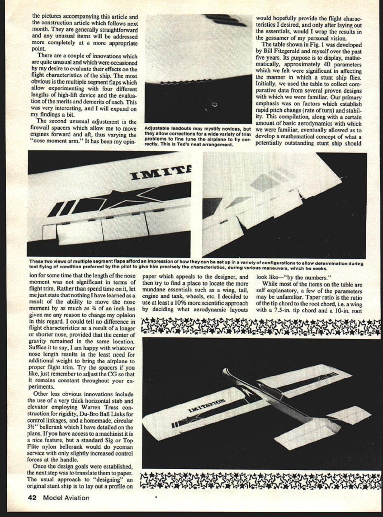
Edition: Model Aviation - 1979/09
Page Numbers: 39, 40, 41, 42, 43, 44, 45, 114, 115, 116
IT pretty Shareen lsTedsbetterhalfWCdOflt Uknow what makes Imitation thing beauty its own right 59-inch ship profile variation true profile beginning just forward cockpit Desinn te 2 Editors Note order reenforce read ers impressions authors discussion design development borrowed photos intended next months construction feature plans will repeatedso sure keep issue reference Both installments include vast amount priceless information relating photos uur necessarily generalized captions instance justice author knowledgable stunt flier THE Imitation designed flying testbed explore soundness num ber aerodynamic philosophies experimenting through Citation series competition stunt air craft addition intended used discriminating stunt pilot in-depth exploration aerody namic philosophies being evolved through authors Citation series aircraft Article plans Imitation appear next month Ted Fancher test suitability stunt purposes variety currently available very powerful Schnuerle-ported 40 engines Citation although has enviable contest record including third second last two National Championships does have couple significant shortcomings felt corrected before investing time effort new competition airplane First foremost too much thorough bred although capable outstanding performance entirely too critical trim adjustments weather conditions necessary spend con siderable time before contest trimming adjusting peculiarities contest site instance before qualifying 78 Lake Charles Nats tear September 1979 39 out almost full ounce nose weight order regain same degree crispness corners had cool heavy air Northern California addition necessary explore whole series props find would allow crisp maneuvers result excessive air speeds single perplexing prob lem however Citations inability come out corner hard flat time altogether too sensitive handle adjustment center gravity location pM has literally nursed around cor ners occasional bobble avoided Because need resolve problems decided design easily built test ship would allow investi gate possible solutions meaningful such design would have combine ease construction truly competitive planform would nearly possi ble display characteristics state art competition stunt plane Such combination would have include An inverted engine appropriately lo cated fuel system ie directly behind engine adjustable vertical allow trimming consistent engine runs addition should possible easily interchange engines explore potential replacements venerable ST 46 planform je wing span wing area mo ment arms horizontal stab elevator area aspect ratios etc would have identical competition plane same size although would easy matter build simple profile significantly lighter competition ship temp tation avoided lighter wing loading would make results tests meaningless translation heavier ship compliance basic para meters Imitation came off building board sporting semi full fuselage front end supporting Kraft-Hayes 1CM40 engine mount easily removable accommodate variety engines cut out incorporated nose allow fuel tank properly located allowance made space shim tank either up down Aerodynamically Imitation features 59-in wing span 631 sq area results aspect ratio 55 unfamiliar term aspect ratio mathematically defined length wing span squared divided area constant chord straight tapered wings wing area divided average chord comparatively long tail employed along large horizontal stab elevator 140 sq 222% wing area No attempt made keep weight down result Imitation came out weighing 50 53 ounces de 40 Model Aviation nice touch lathe metal plate attaches 4 flathead screws over landing gear wire mounts normal fashion simple block assemblyControl Specialties item right wing tip ShOwing nylon bolt variable weight box flap pin Mul tiple segment flaps allowed experimentation four different lengths high-lift device evaluation merits demerits Teds findings given text Teds handle adjustable both lines picture makes clear manufacturers re minder notto fly nearoverhead power lines excellent safety remindersome require 59 0123456 w-J-w-j-J pending weight engine translates wing loading 114 121 oz/sqftactually slightly heavy competitive range Citation inw stance has wing loading 110 ozIsqft addition basic requirements now mandatory adjustable fea tures would have included order TED FANCHERS IMITATION rAD achieve optimum flight trim personal approach such things adjustable line guides tip weight tail weight control ratios forth detailed plans T C/2 CI MGC CL MGC 4CI L KCI FIGURE m LIFT VERSUS ANGLE OF ATTACK AND AIRFOIL CAMBER RELATIVE~ LOW LIFT AIRFLOW BOOY ANGLE -0 FLAP DEFLECTION RFOIL UNCAMBERED NON-LIFTING SECTION ANGLE OF ATTACK-OF FIGURE II LOCATING ThE MEAN DEOMETRIC CHORD I LAYOUT THE TOP VIEW OF THE WING 2 EXTEND ThE ROOT CHORD IN EITHER DIRECTION FOR DISTANCE EQUAL IN LENGTH TO THE TIP CHORD 3 EXTEND THE TIPCHORD THE OPPOSITE DIRECTION FOR QSTANCE EQUAL IN LENGTh TO THE ROOT CHORD 4 CONNECT THE ENDS OF THE EXTENSIONS MADE IN STEPS 2 AND 3 5 CONNECT MID POINTS OF ROOT AND TIP CHORDS THE MGC ISA UNE RALLEL TO THE ROOT CHORD LOCATED AT THE LOCUS OF THE LINES DRAWN IN STEPS 4 AND S ASSUMED CENTER OF LIFT IS NOW LOCATED 1/3 OF THE I-IORO LENGTH AFT OF THE LEADING EDGE AT THE MGC RIV RE AIRFLOWMODERATE LIFTAIRFLOW BODY ANGLE LAP DEFLECTION AIRFOIL-UNCAMBERED NON-LIFTING SECTION ANGLE OFATTACI- 10 DERIVATION OF CONTROL EFFECTIVENESS RATlOS ERs TAlLER AXL WING VOL FLAP ER A2X L2 WING VOL AXLA2XLz TOTALCONTROLERSWING VOL WHERE TAIL AREA A2 FLAP AREA CL WING TO CL TAIL IN INCHES CL WINGTO FLAPHINGELIN IN INCHES C A1 WING VOL MGC X WING AREA FIGURE ] BASIC AIRFOIL TERMINOLOGY NOTES ON SYMMETRICAL AIRFOILS CHORD AND CAMBER LINES COINCIDE ThICKNESS AND ITS LOCATION ARE EXPRESSED AS PERCENrAGE OF THE CHORD IE IB% THICK AT 25% OF THE CHORD LOCATION h-oF IAAXI THCKILSS ICAMBER ILINETRAILING EDGE MAX THICKNESS ----LEADING EDGE LEADINGCHORD LINE EDGE RADUS LEGEND CHORD LINE CAMBER LINEcC ANGLE OF ATTACKhI IS HIGH LIFT BODY ANGLE LAP DEFLECTION IRFOIL-CAMBERED LIFTING SECTION ANGLE OF ATTACK-IS September 1979 41 pictures accompanying article construction article follows next month generally straightforward unusual items will addressed completely appropriate point couple innovations quite unusual occasioned desire evaluate effects flight characteristics ship obvious multiple segment flaps allow experimenting four different lengths high-lift device evalua tion merits demerits very interesting will expand findings bit second unusual adjustment firewall spacers allow move engines forward aft thus varying nose moment arm has opin ion some time length nose moment significant terms flight trim Rather spend time let just state nothing have learned result ability move nose moment much has given reason change opinion regard could tell no difference flight characteristics result longer shorter nose provided center gravity remained same location Suffice say am happy whatever nose length results least need additional weight bring airplane proper flight trim Try spacers like just remember adjust CG remains constant throughout ex periments Other less obvious innovations include use very thick horizontal stab elevator employing Warren Truss con struction rigidity Du-Bro Ball Links control linkages homemade circular 3 bellcrank have detailed plans have access machinist nice feature standard Sig Top Flite nylon bellcrank would yeoman service slightly increased control forces handle Once design goals established next step translate paper usual approach designing original stunt ship lay out profile would hopefully provide flight charac teristics desired after laying out essentials would wrap results gossamer personal vision table shown Fig developed Bill Fitzgerald myself over past five years Its purpose display mathe matically approximately 40 parameters felt significant affecting manner stunt ship flies Initially used table collect com parative data several proven designs familiar primary emphasis factors establish rapid pitch change rate turn stabil ity compilation along certain amount basic aerodynamics familiar eventually allowed us develop mathematical concept what potentially outstanding stunt ship should look likeby numbers items table self explanatory few parameters may unfamiliar Taper ratio ratio tip chord root chord ie wing 75-in tip chord 10-in root 42 Model Aviation Adjustable leadouts may mystify novices allow corrections wide variety trim problems fine tune airplane fly cor rectly Teds neat arrangement two views multiple segment fisps afford impres,., .un uu 561 up variety conTigurations show determination during test flying condition preferred pilot give him precisely ins cnaracteristics during various maneuvers seeks paper appeals designer try find place locate mundane essentials such wing tail engine tank wheels etc decided use least 10% scientific approach deciding what aerodynamic layouts chord would have taper ratio 75% MGC Mean Geometric Chord graphically derived station along span closely approximates Mean Aerodynamic Chord See Fig II point results aerodynamic forces may assumed concentrated practical purposes simple tapered wing planforms Mean Aerodynamic Chord MGC may considered identical design purposes have arbitrarily designated point 33% aft leading edge MGC Center Lift arbitrary point used datum reference point design parameters followprimarily dealing moment arms may well say now though may con sidered heresy classic measure moment arms ie back prop wing leading edge crack crack flaps elevators practically no value Because takes no cognizance different planforms top view wing tail shape relationships aspect ratios can seen instance 15-in tail moment 600 sq airplane 54-in span bears little resemblance 15-in tail moment 600 sq airplane 65in wing swept back 200 merit such comparisons must based common reference design discussion purposes arbitrary ref erence should established have chosen use point titled Center Lift table Harkening back comments regard ing adjustable nose length note have result test bothered measurement nose moment just dont think its significant Argue love Volume wing mathematical product wing area multiplied Mean Geometric Chord used later calculation regarding stabillty control effectiveness using wing volume force calculations rather just wing area get measure effectiveness aspect ratio determining control re sponse As aspect ratios decrease ie MGC becomes larger wing volume becomes larger effectiveness tail surfaces both control stability decreases later will notice area covering flaps becomes somewhat cluttered due use four different flap sizes Rather try totally digest numbers suggest read conclusions experiment later article both flap tail sections table have entry flap/tail volume might appropriately called flap/tail percentages reflect comparative size flaps tail comparison wing three Effectiveness Ratios Flap Tail Total Control developments work solely compari son plane another See figure IV have no mathematical basis valid ity other purpose What tempted illustrate potential forces developed tail flaps affect flight path wing tail virtue lift develops multiplied its September 1979 43 Above We wont comment tne coupling flaps elevators illustrated photo cause author goes deeply other matters both article next months construction feature point interest fairlead eliminate pushrod deflection Below flap horn set up allow throw adjustment short/long pushrods pushrods threaded use Du-Bro ball links -oz Sullivan nylon oval slant tank taken out show contours cutout mounting Arrangement used plans published distance datum capable applying X amount force achieve change angle attack flaps virtue same two factors able apply Y amount leverage affect angle attack however opposite direction Both forces acting wing has certain amount reluctance change direction based pri marily its size shape Therefore subtracting restraining force flaps force tail relating result wing volume able derive number roughly approxi mates ability given airplane change directions As number gets larger ability airplane corner briskly increases As will note later discussion regarding variable length flap experiments validity ap proachif mathematical soundness formulais totally supported dislike Im sure designer tells did something certain way very good reason doesnt want bore technicalities very fair him pass cloak ignorance readers Therefore Im going run down conception what stunter should look like general least cursory explanation feel particu lar characteristic employed Imita tion important disagree thats great Its about time stunt world some controversy over something sides judging First feel should using higher aspect ratios stunt ships Higher aspect ratios result significantly lower induced drag high lift-drag situations such square corner Rapid drag build up causes speed decay demands greater horsepower engine Reduce drag build-up corners need automatic four cycle/two cycle engine run becomes less demanding Since induced drag comes combination tip vortices miniature horizontal tornadoes formed tips high-pressure air bottom wing being drawn around tip low-pressure area top wing down-wash tend ency high velocity air particles upper surface wing continue downward beyond trailing edge can reduced moving tips further apart good argnment raked style wing tips versus flat plate types reducing length chord wing given area ie higher aspect ratios some negative results higher aspect ratios Maintaining struc tural integrity longer wing difficult care must taken avoid warps effects pronounced terms performance lowered induced drag results aircraft has increased sensitivity power prop changes have found necessary use large diameter lower-than-normal pitch props maintain proper lap times control increased tendency accelerate consecutive maneuvers Zinger 12X5s 1 2X4s seem ideal resulting lap times 55 57 seconds per lap nicely controlled airspeed maneuvers 62-foot lines have also doing some testing Bobby No 1 Hunts three-bladed Rev-Ups shows some promise Secondly tails should significantly longer both stability turn perfor mance effect stability relatively easy perceive dont believe open serious debate other hand large school thought argue merits shorter tails because get kick closer CG throw plane around corner understand concept error necessary understand concept moment arm effect has pitch change angle attack lift produced resultant body angle Assume entering first corner inside square loop What judges looking simplest terms 90degree change flight path concept change body angle result air pushing against deflected elevator 44 Model Aviation could almost write book about things evident discerning stunt pilots eye hinging jam nut clevis easily accessible compartment flexibility use weights Deep cheek blocks thatcontourthe basic profile afford opportunityto neatly submerge exposed tank mount carbon/glass Kraft-Hayes item familiar RC people Firewall spacers allow up movement Fancher regards essential CG remain specified causing aircraft rotate about center gravity simply true chronological order what fact takes place following must understood tail func dons deflecting air rather producing lift same way lifting surface ie through difference pres sure between top bottom airfoil lift thus produced multiplied its distance aircrafts center gravity product lift force ap plied multiplied forces distance center gravity moment arm Increase either resultant force increases force thus applied causes aircraft pitch up resulting increased angle attack turn results increased lift wing Assuming sufficient thrust overcome induced drag comes increased lift can seen aircraft will continue increase angle attack long force continues applied tail rate proportional degree force being applied until such time force removed plane continues along newly achieved flight path Since air craft has inherent desire remain motion along given path until displaced outside force obvious greater force applied rapid will resulting change flight path Therefore longer tail moments will result tighter turns less lift drag shorter tails Thirdly aircraft size increases find control inputs necessary deflect larger control surfaces against slipstream becoming greater well compara tively small man such myseW increased requirements muscle center circle become substantial especially light need hundreds practice flights year problem can attacked both aerodynamically mechanically Aerodynamically forces can reduced both reducing proportion surface deflected ie smaller elevators flaps keeping chord deflected surfaces short reason able easily demonstrate latter phe nomenon try deflecting rectangular object such piece wood approxi mately four times long wide 4 1 aspect ratio both lengthwise widthwise against slipstream outside car window 55 mph will notice consi derably resistance attempt deflect surface lengthwise demonstrates significantly reduced con trol leverage required high aspect ratio control surfaces Because fact such long narrow lift device efficient creates less drag short fat ones feel flaps should limited between 15 20% wing chord given station wing Imitation results flaps 17% chord stations proponents large elevators probably questioning sanity suggest smaller ones Again important remember force causes pitch change comes lift produced entire tail solely amount surface deflecting slip stream Therefore what looking efficient lift-producing surface Prob ably efficient tail would have elevator comprised approximately 25% total tail surfacesomething like Flite Streak everyone knows will outmaneuver conventionaltailed Ringmaster hands down however some compromise necessary terms drag stability makes larger optimum elevators result aircraft stable maneuvering Since moving cen ter drag aft stabilizing its effect since certain amount drag comes hand hand lift tail produces maneuver apparent sacrifice little drag can build airplane controllable maneuver ing has less tendency over shoot headings same reason thicker tail employed along lower aspect ratio Such tail wont efficient terms maximum rate turn will come close net effect will enhance overall flyability air plane As result compromises Imitation has tail totals 140 sq 55% stabilizer 45% eleva tor aspect ratio tail 45 1 Mechanically control forces can re duced achieving increased mechanical advantage over aerodynamic resistance Continued page 114 September1979 45 Ted makes no comment stooge readers have asked make onethet include explanatory picture Stooge anchored ground string pulls release pin Voile1 Some variety 40-size engines used during thedifferent firewall spacers required Metal tank appears picture does muffler pressure arrangement fYOYflO PROPELLERS Madeof polyester boil orcolor Go GRISH propeller True helical pitch airfoil win-power 2 Blade Tractor 53each 54535430d 636435d 74767850 84868865d 949697 9810-410685dneeds 114116118 Si 124125126$150 2 Blade Pasher 543 54-4636435 86854 96106Si 3 Blade Tractor 53 63 64504 3 Blade Pasher 63s043 mmBlade Metallic Aluminum color Tractor ifiB Si 86885125 96061045150 Pusher06 $150 Sizes pitches GRISI4 LARGE WOOD PROPELLERS HARDWOOD too hard minimizes chance costly plane engine damage True pitch airfoil fully finished balanced ready coating 318 BOREALL SIZES IN18 $7 68&lOPITcH 20 8 22 10 24 13 REYCKASIR little piece electronic wizardry quickly easiiy reverses direction servo travel plugged between receiver servo will work positive pulse servos e four wire Connectors NOT furnished Available unassembled kit form assembled tested 14K104Ace Servo Reverser kit $795 14K104CAce Servo Reverser assy $1150 details send $1 latest catalog Add $50 1st class return $1 hand ling direct orders 816 584-7121 IAE E/IrnJ Box ShE HIGGINSVILLE MO 64037 NEW ERA PUBLICATION CUSTOM TUNED ENGINESAEROBATIC AIRPLANES BY PORT C MORRISON COMPETITION ACCESSORIES4U PAGES I 52 PHOTOS Cox 049L051 SpecialistsU OE1AILEO DRAWINGS brochure send 15c stamp toOnly 6395 PLUS SOft POSTAGE Kuslom Kraftsmanship BrochureCATALOGS 3100 REPLA-TECH Box 2699 Laguna Hills CA 92653INTERNATIONAL icc 714 830-51624U500 MC KENZIE HWY VEGA OREGON 9745E several hours Texas covered monstrous high pressure system day surely some drift expected point turned TV discovered looking weather balloon released morning Palas tine TX National Science Foundation jumbo 450 feet diameter containing 40 million cu ft helium floating 23 miles overhead am still amazed unaided visual identifi cation object 120000 feet Apparently others switchboards Dallas went wild after sundown reflected sunlight produced pinkish cast side polyethylene balloon leading thousands UFO reports Dee B Mathews 506 S Walnu Greensburg KS 67054 writing advertisers mention read about Model Aviation mitation/Fancher continued page 45 deflection Simply stated means longer control horns bigger bellcrank Imitation uses homemade 3 circular bellcrank maintains its full 1 fulcrum entire range control movement pushrod exits bellcrank 09 bellcrank axis attached DuBro Ball Link flap horn inch flap hinge line flap elevator pushrod located 075 inches respective hinge lines classic one-to-one flap elevator ratio conven tional horn employed elevator allow use elevator slop necessary now appears ball links could have used throughout long tail moment large surface area tail have proven provide stability could hope handle provides finishing touch control system modified Custom Master Flight Handle designed Bob Baron produced Gene Martine Custom Master Products 5424 Oliver Street S Jacksonville FL 32211 Before leaving subject control surfaces lets talk bit about variable span flaps effect flight characteristics Imitation First lets once rid ourselves desire think flaps separate distinct wing Wing flaps simply part wing happen attached such way may moved up down about hinge line doing make substantial changes characteristics airfoil Reference Figure III changes significantly affect amount lift wing given area capable producing classic symmetrical stunt airfoil often referred non-lifting section inas much its top bottom surfaces mirror images result camber line line drawn equidistant top bottom surface straight line Theoretically such section zero angle attack would produce no lift due being no differential velocityand fore pressure above below wing Now hinge aft 15 20% wing surface deflect downward will have altered number things First have instantly changed uncambered non-lifting aiifoil cambered lifting Also since measure airfoils angle attack defined angle between relative wind line between leading edge trailing edge chord line have concurrently increased angle attack two items acting concert have made quantum increase amount lift produced same airfoil its natural symmetrical state apparent amount flap area important factor determin ing amount additional lift produced Rather percentage total wing span equipped high lift device significant other words wing has 15% its total area flap along its full span will produce signifi cantly lift same wing 15% its total area flap concen trated say s span So far well good Weve seen can apparently get something nothing almost instantaneously just bending back wing however small fly ointment buzzes around fact center lift almost exception located some what aft center gravity Addition ally center lift will move further aft deflection flaps concur rent increases lift angle attack As result divergent location 114 Model Aviation styles AT YOUR DEALER RIGHT HAND TRACTOR NEW SIZE IN B & 10 PITCH 26 $16 GRISH BROS ST JOHN INDIANA 46373 * SEND STAMPED SELF ADDRESSED ENVELOPE FOR COMPLETE STATISTICS AND FULL SIZE DRAWINGS DUBRO PRODUCTS INCORPORATED ILL 6CO84 centers lift gravity moment produced between two whenever either increased case classic stunt configuration center lift aft force manifests itself negative pitching moment wants pitch nose direction opposite desired change pitching moment adversely affects ability make rapid changes attitude therefore best interests minimize its effects seriously search elusive rule-book corner Since pitching moment again product lift times its distance center gravity minimizing its effect must come through reduction other Any reduction lift would have come through decrease flap size since need lift can generate its reduction viable solution pitching moment dilemma decrease arm achievable variety ways Higher aspect ratios inherently have less distance between CL CO Smaller chord flaps also result less rearward movement CL deflection third possible method shortening arm move CL forward attempt accomplish high point airfoil Imitation placed 22% chord full span full 8% further forward Citations 30% Finally classic method merely mov ing CO aft always available through addition tail weight design such Imitation its high stability coefficient ie large tail long arm much amenable such solution can withstand much furth aft CG becoming unstable addi tion large tail long moment arm provide leverage necessary overcome adverse pitching moment fore retain adequate turn potential full span flaps opinion last two itemsmoving C/L forward ability move CG aft still retain adequate stabilityare pri marily responsible improvement Imitations ability come out corners hard flat compared Citation silver lining pitching moment cloud however negativeor purposes opposing-pitching mo mentis stabilizing its effect Imagine briskly rotating bicycle wheel no resistance trying stop precisely predetermined point Now mentally repeat same exercise light moderate brake pressure resisting efforts imagine much easier would stop precisely pitching moment wing acts same manner resist stabilize efforts change its attitude against its wishes Flight tests Imitation varying flap sizes seem back up foregoing theories initially flown innermost sections flap operable flights configuration spectacu lar came corners 60% span flapped total 11% total wing area movable pitching moment minimal huge lever age tail plane could literally leap through corners Unfortunately round maneuvers suffered nearly uncontrollable tendency wander Minor control inputs would cause noticeable pitch changes mani fested visible flat spots rounds As increasing amounts flap made oper able extremes explosive corner marginal tracking began moderate Now corners although still impressively tight became much controllable pre cise exits easier As pitching moment additional flap increased plane became much easier fly through round maneuvers tracking improved remarkably experiment flaps made tempting build competition airplane same feature windy weather G forces build up consecutive maneuvers would tempting able fix some flap reduce adverse pitching moment hard corners thus reduce eliminate loss corner normally associated flying wind think though temptation should avoided because its adverse effect round maneuvers fact would never really come know plane intimately Although learned great deal experiment still dont feel confident could say much flap ideal will cautiously generalize little tco much probably better too September1979 115 ENGINE HAS GOT IT FUEL TUBING CLEAR NEOPRENE SUPER BLUE SILICONE FUEL AVAILABIE OFF ThE ROLL OR PACIAGED IN 2 LENGTHS CATPKG NOFUEL TUBINGPRICE 2182 FT CLEAR VINYL-SM.30 2192 FT CLEAR VINYL-MED.40 2202 FT CLEAR VINYL-LG.50 2212 FT SILICONE-SM.90 2222 FT SILICONE-MED$110 2232 FT SILICONE-LG$150 2242 FT NEOPRENE-SM.60 2252 FT NEOPRENE-MED.80 2262 FT NEOPRENE-LG.90 ir SLOW POWERFUL FLIGHT IS ACHIEVED WITH THIS UNIT MAKING YOUR AIRCRAFT LOOK AND SOUND REALISTIC RPMS RANGING FROM 600-5000 DEPENDING ON ENGINE AND PROPQOt PItOo r SWING 18 20 22 AND 24 PROPS WITH 8 OR 10 PITCH WITH YOUR 60 ENGINE NNOUNCINGThe New Instant-Dry f Adhesive Process K Ffl ToSheetFoam Wing Cores new product Corefilm replaces using white glue epoxy contact cement sheeting foam wing cores Corefilm rough thin lightweight mylar tape has ooated both sides contact adhesive Corefilm ready instant use After oovering wing core 11/2 strips corefilm remove paper backing set plywood balsa sheeting material place press foam core bond instant Corefilm flight tested gliders power ships tough mylar film provides strapping tape effect both top bottom has proven desirable superior quality Corefilm comes 1% wide 36 yard rolls roll will cover over 1900 sq 13 sq dealer direct Write brochure complete line BILL 19216 Calvert Street Reseda CA213/344-6391 Quiet Power -Tatone Makes new super quiet K&B 40 R/C muffler requires machined fit exhaust stack cover Easy no exhaust plugs fittings adaptors Muffler exposed holes Just bolt on.thats itl Will reduce noise 10 12 decibels little no loss rpms Noise cancelled interposing sound waves eRadi cal free flow expansion chamber angled blow exhaust away fuselage attach provision pressure fitting Also available ENYA 29 35 40 45 OS MAX 30 35 40 SUPER TIGRE 021 35 46 Add $100 extra above engines specify type Mounting strap screw included $1295 No 306 Add $125 postage handling CA residents add 6% tax Dealer inquiries 1931 Gee Bee Super Spo1Scale General Arrange-I - ment Drawing Catalog 25c W T Bill Given MODERNISTIC MODELS PO BOX 6974 ALBUQ NM 87197 little higilpoints design philosophy resulted Imitation say plane success would unfair understatement facts respects best flying plane have flown terms tight precise corners has few peers experimental features tested Imitation successful results now being incorporated new competition ship Excitation Because relative ease construc tion Imitation should reasonable project builder few profiles under belt Due ts outstanding flying capabilities perfect selection contest machine beginners GET ORGANIZED set 4 st.d ties 00kM Osr 4 years yes taole II eragazeres 4 MAO FILES $495 Seod 5496 pMe $1 00 postage wd taneag DaM iwnuemma PO Box 3M-K DOVER NH 00000 advanced fliers Any builder desires far better average plane practice impressive Sunday barnstorming ought take close look Continued Suggested Reading Fundamentals Aircraft FlightFred erick K Teichmann Hayden Book Co Inc Rochelle Park NJ Aerodynamics forNavalA viatorsIssued Office Chief Naval Opera tions Aviation Training Division Primar ily Chapter Pages 1 through 95 FLY SAFELY CL Speed/Hempel continued tram page 47 eral Speed supplies Rossi engine parts John Newton 2154 Los Padres Drive Rowland Heights CA 91748 lane parts Chuck Schuette-design asymmetric sidewinder Questions concerning article FAI Speed general may addressed Charles Lieber 725 Signal Light Rd Moorestown NJ 08057 Gene Hempel 301 North Yale Dr GarlantL TX 77459 CL Scale/Gretz continued page 48 authentically contoured spinners available parts castof gray epoxy resin ready-to-paint no priming extensive sanding required samples saw ap peared very accurately researched duplicated displayed excellent workmanship Also available firm hand-carved laminated wood scale props suitable WWl vintage kits market also come ready-to-finish include metal hub plates scratch-builders Keeler will make custom props either cast resin wood providing can furnish adequate scale documenta don should include diameter fullsize prop photos drawings possible materials will returned upon completion prop RingAroundthe. Cockpitl oldest tricks scale modeling book using fuel line tubing simulate padded edging normally found around rim open cockpits vintage full-scale aircraft com monly referred cockpit coaming building CL Sport Scale PT-i 9 became reacquainted familiar technique jotted down few notes may interest coaming around cockpits actual full-size PT-19 duplicating made padded black leather type typical older open cockpit aircraft may find some homebuilt types today will have foam rubber edging case need find brand tubing has right diameter wall thickness give correct degree size roundness found some W ID IA OD black neoprene rubber tubing formerly marketed VECO looked just right 10 feet away 1/6th scale modeL After finish complete used sharp #11 X-acto knife cut cockpit openings final shapeThen flat black anti-glare panel painted dry cut piece tubing cockpit slightly longer figure actually needed Use sharp blade again cut through tubing lengthwise along side can opened up slipped over cockpit edge trial fit tubing model first time glue Start end very carefully go way around making certain tubing isflrinly pushed up against balsa edge before cutting itto final length youre completely satisfied will fit desired take off mix up batch slow drying overnight epoxy glue Use piece wire work epoxy inside tubing Slip tubing back place model use plenty pins secure balsa cockpit until glue dries tubing using necessary push pins firmly withdraw just slightly holding tubing back fingers avoid leaving permanent dimple tubing after epoxy 116 Model Aviation
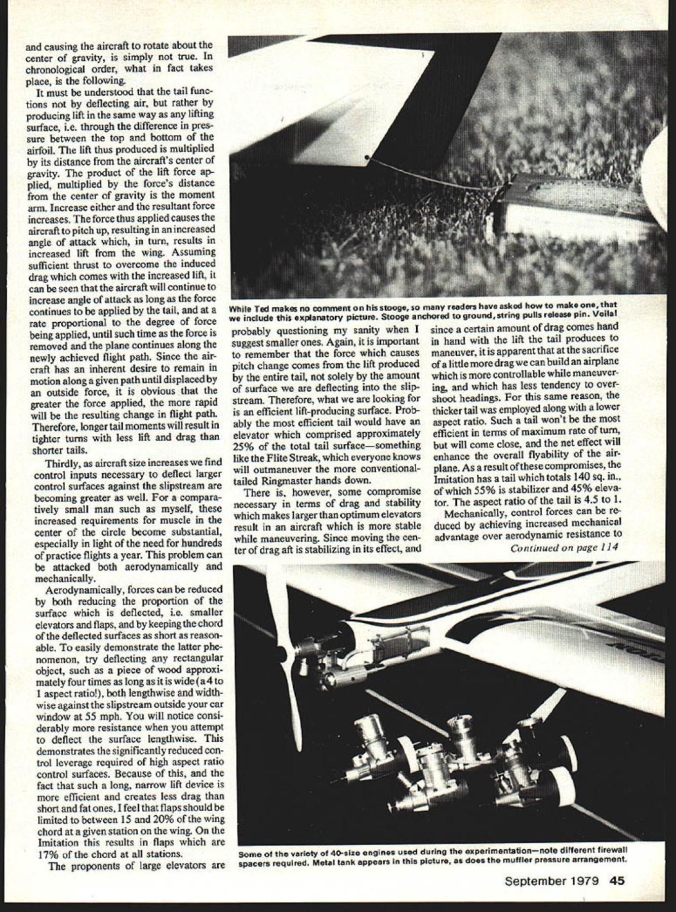
Edition: Model Aviation - 1979/09
Page Numbers: 39, 40, 41, 42, 43, 44, 45, 114, 115, 116
IT pretty Shareen lsTedsbetterhalfWCdOflt Uknow what makes Imitation thing beauty its own right 59-inch ship profile variation true profile beginning just forward cockpit Desinn te 2 Editors Note order reenforce read ers impressions authors discussion design development borrowed photos intended next months construction feature plans will repeatedso sure keep issue reference Both installments include vast amount priceless information relating photos uur necessarily generalized captions instance justice author knowledgable stunt flier THE Imitation designed flying testbed explore soundness num ber aerodynamic philosophies experimenting through Citation series competition stunt air craft addition intended used discriminating stunt pilot in-depth exploration aerody namic philosophies being evolved through authors Citation series aircraft Article plans Imitation appear next month Ted Fancher test suitability stunt purposes variety currently available very powerful Schnuerle-ported 40 engines Citation although has enviable contest record including third second last two National Championships does have couple significant shortcomings felt corrected before investing time effort new competition airplane First foremost too much thorough bred although capable outstanding performance entirely too critical trim adjustments weather conditions necessary spend con siderable time before contest trimming adjusting peculiarities contest site instance before qualifying 78 Lake Charles Nats tear September 1979 39 out almost full ounce nose weight order regain same degree crispness corners had cool heavy air Northern California addition necessary explore whole series props find would allow crisp maneuvers result excessive air speeds single perplexing prob lem however Citations inability come out corner hard flat time altogether too sensitive handle adjustment center gravity location pM has literally nursed around cor ners occasional bobble avoided Because need resolve problems decided design easily built test ship would allow investi gate possible solutions meaningful such design would have combine ease construction truly competitive planform would nearly possi ble display characteristics state art competition stunt plane Such combination would have include An inverted engine appropriately lo cated fuel system ie directly behind engine adjustable vertical allow trimming consistent engine runs addition should possible easily interchange engines explore potential replacements venerable ST 46 planform je wing span wing area mo ment arms horizontal stab elevator area aspect ratios etc would have identical competition plane same size although would easy matter build simple profile significantly lighter competition ship temp tation avoided lighter wing loading would make results tests meaningless translation heavier ship compliance basic para meters Imitation came off building board sporting semi full fuselage front end supporting Kraft-Hayes 1CM40 engine mount easily removable accommodate variety engines cut out incorporated nose allow fuel tank properly located allowance made space shim tank either up down Aerodynamically Imitation features 59-in wing span 631 sq area results aspect ratio 55 unfamiliar term aspect ratio mathematically defined length wing span squared divided area constant chord straight tapered wings wing area divided average chord comparatively long tail employed along large horizontal stab elevator 140 sq 222% wing area No attempt made keep weight down result Imitation came out weighing 50 53 ounces de 40 Model Aviation nice touch lathe metal plate attaches 4 flathead screws over landing gear wire mounts normal fashion simple block assemblyControl Specialties item right wing tip ShOwing nylon bolt variable weight box flap pin Mul tiple segment flaps allowed experimentation four different lengths high-lift device evaluation merits demerits Teds findings given text Teds handle adjustable both lines picture makes clear manufacturers re minder notto fly nearoverhead power lines excellent safety remindersome require 59 0123456 w-J-w-j-J pending weight engine translates wing loading 114 121 oz/sqftactually slightly heavy competitive range Citation inw stance has wing loading 110 ozIsqft addition basic requirements now mandatory adjustable fea tures would have included order TED FANCHERS IMITATION rAD achieve optimum flight trim personal approach such things adjustable line guides tip weight tail weight control ratios forth detailed plans T C/2 CI MGC CL MGC 4CI L KCI FIGURE m LIFT VERSUS ANGLE OF ATTACK AND AIRFOIL CAMBER RELATIVE~ LOW LIFT AIRFLOW BOOY ANGLE -0 FLAP DEFLECTION RFOIL UNCAMBERED NON-LIFTING SECTION ANGLE OF ATTACK-OF FIGURE II LOCATING ThE MEAN DEOMETRIC CHORD I LAYOUT THE TOP VIEW OF THE WING 2 EXTEND ThE ROOT CHORD IN EITHER DIRECTION FOR DISTANCE EQUAL IN LENGTH TO THE TIP CHORD 3 EXTEND THE TIPCHORD THE OPPOSITE DIRECTION FOR QSTANCE EQUAL IN LENGTh TO THE ROOT CHORD 4 CONNECT THE ENDS OF THE EXTENSIONS MADE IN STEPS 2 AND 3 5 CONNECT MID POINTS OF ROOT AND TIP CHORDS THE MGC ISA UNE RALLEL TO THE ROOT CHORD LOCATED AT THE LOCUS OF THE LINES DRAWN IN STEPS 4 AND S ASSUMED CENTER OF LIFT IS NOW LOCATED 1/3 OF THE I-IORO LENGTH AFT OF THE LEADING EDGE AT THE MGC RIV RE AIRFLOWMODERATE LIFTAIRFLOW BODY ANGLE LAP DEFLECTION AIRFOIL-UNCAMBERED NON-LIFTING SECTION ANGLE OFATTACI- 10 DERIVATION OF CONTROL EFFECTIVENESS RATlOS ERs TAlLER AXL WING VOL FLAP ER A2X L2 WING VOL AXLA2XLz TOTALCONTROLERSWING VOL WHERE TAIL AREA A2 FLAP AREA CL WING TO CL TAIL IN INCHES CL WINGTO FLAPHINGELIN IN INCHES C A1 WING VOL MGC X WING AREA FIGURE ] BASIC AIRFOIL TERMINOLOGY NOTES ON SYMMETRICAL AIRFOILS CHORD AND CAMBER LINES COINCIDE ThICKNESS AND ITS LOCATION ARE EXPRESSED AS PERCENrAGE OF THE CHORD IE IB% THICK AT 25% OF THE CHORD LOCATION h-oF IAAXI THCKILSS ICAMBER ILINETRAILING EDGE MAX THICKNESS ----LEADING EDGE LEADINGCHORD LINE EDGE RADUS LEGEND CHORD LINE CAMBER LINEcC ANGLE OF ATTACKhI IS HIGH LIFT BODY ANGLE LAP DEFLECTION IRFOIL-CAMBERED LIFTING SECTION ANGLE OF ATTACK-IS September 1979 41 pictures accompanying article construction article follows next month generally straightforward unusual items will addressed completely appropriate point couple innovations quite unusual occasioned desire evaluate effects flight characteristics ship obvious multiple segment flaps allow experimenting four different lengths high-lift device evalua tion merits demerits very interesting will expand findings bit second unusual adjustment firewall spacers allow move engines forward aft thus varying nose moment arm has opin ion some time length nose moment significant terms flight trim Rather spend time let just state nothing have learned result ability move nose moment much has given reason change opinion regard could tell no difference flight characteristics result longer shorter nose provided center gravity remained same location Suffice say am happy whatever nose length results least need additional weight bring airplane proper flight trim Try spacers like just remember adjust CG remains constant throughout ex periments Other less obvious innovations include use very thick horizontal stab elevator employing Warren Truss con struction rigidity Du-Bro Ball Links control linkages homemade circular 3 bellcrank have detailed plans have access machinist nice feature standard Sig Top Flite nylon bellcrank would yeoman service slightly increased control forces handle Once design goals established next step translate paper usual approach designing original stunt ship lay out profile would hopefully provide flight charac teristics desired after laying out essentials would wrap results gossamer personal vision table shown Fig developed Bill Fitzgerald myself over past five years Its purpose display mathe matically approximately 40 parameters felt significant affecting manner stunt ship flies Initially used table collect com parative data several proven designs familiar primary emphasis factors establish rapid pitch change rate turn stabil ity compilation along certain amount basic aerodynamics familiar eventually allowed us develop mathematical concept what potentially outstanding stunt ship should look likeby numbers items table self explanatory few parameters may unfamiliar Taper ratio ratio tip chord root chord ie wing 75-in tip chord 10-in root 42 Model Aviation Adjustable leadouts may mystify novices allow corrections wide variety trim problems fine tune airplane fly cor rectly Teds neat arrangement two views multiple segment fisps afford impres,., .un uu 561 up variety conTigurations show determination during test flying condition preferred pilot give him precisely ins cnaracteristics during various maneuvers seeks paper appeals designer try find place locate mundane essentials such wing tail engine tank wheels etc decided use least 10% scientific approach deciding what aerodynamic layouts chord would have taper ratio 75% MGC Mean Geometric Chord graphically derived station along span closely approximates Mean Aerodynamic Chord See Fig II point results aerodynamic forces may assumed concentrated practical purposes simple tapered wing planforms Mean Aerodynamic Chord MGC may considered identical design purposes have arbitrarily designated point 33% aft leading edge MGC Center Lift arbitrary point used datum reference point design parameters followprimarily dealing moment arms may well say now though may con sidered heresy classic measure moment arms ie back prop wing leading edge crack crack flaps elevators practically no value Because takes no cognizance different planforms top view wing tail shape relationships aspect ratios can seen instance 15-in tail moment 600 sq airplane 54-in span bears little resemblance 15-in tail moment 600 sq airplane 65in wing swept back 200 merit such comparisons must based common reference design discussion purposes arbitrary ref erence should established have chosen use point titled Center Lift table Harkening back comments regard ing adjustable nose length note have result test bothered measurement nose moment just dont think its significant Argue love Volume wing mathematical product wing area multiplied Mean Geometric Chord used later calculation regarding stabillty control effectiveness using wing volume force calculations rather just wing area get measure effectiveness aspect ratio determining control re sponse As aspect ratios decrease ie MGC becomes larger wing volume becomes larger effectiveness tail surfaces both control stability decreases later will notice area covering flaps becomes somewhat cluttered due use four different flap sizes Rather try totally digest numbers suggest read conclusions experiment later article both flap tail sections table have entry flap/tail volume might appropriately called flap/tail percentages reflect comparative size flaps tail comparison wing three Effectiveness Ratios Flap Tail Total Control developments work solely compari son plane another See figure IV have no mathematical basis valid ity other purpose What tempted illustrate potential forces developed tail flaps affect flight path wing tail virtue lift develops multiplied its September 1979 43 Above We wont comment tne coupling flaps elevators illustrated photo cause author goes deeply other matters both article next months construction feature point interest fairlead eliminate pushrod deflection Below flap horn set up allow throw adjustment short/long pushrods pushrods threaded use Du-Bro ball links -oz Sullivan nylon oval slant tank taken out show contours cutout mounting Arrangement used plans published distance datum capable applying X amount force achieve change angle attack flaps virtue same two factors able apply Y amount leverage affect angle attack however opposite direction Both forces acting wing has certain amount reluctance change direction based pri marily its size shape Therefore subtracting restraining force flaps force tail relating result wing volume able derive number roughly approxi mates ability given airplane change directions As number gets larger ability airplane corner briskly increases As will note later discussion regarding variable length flap experiments validity ap proachif mathematical soundness formulais totally supported dislike Im sure designer tells did something certain way very good reason doesnt want bore technicalities very fair him pass cloak ignorance readers Therefore Im going run down conception what stunter should look like general least cursory explanation feel particu lar characteristic employed Imita tion important disagree thats great Its about time stunt world some controversy over something sides judging First feel should using higher aspect ratios stunt ships Higher aspect ratios result significantly lower induced drag high lift-drag situations such square corner Rapid drag build up causes speed decay demands greater horsepower engine Reduce drag build-up corners need automatic four cycle/two cycle engine run becomes less demanding Since induced drag comes combination tip vortices miniature horizontal tornadoes formed tips high-pressure air bottom wing being drawn around tip low-pressure area top wing down-wash tend ency high velocity air particles upper surface wing continue downward beyond trailing edge can reduced moving tips further apart good argnment raked style wing tips versus flat plate types reducing length chord wing given area ie higher aspect ratios some negative results higher aspect ratios Maintaining struc tural integrity longer wing difficult care must taken avoid warps effects pronounced terms performance lowered induced drag results aircraft has increased sensitivity power prop changes have found necessary use large diameter lower-than-normal pitch props maintain proper lap times control increased tendency accelerate consecutive maneuvers Zinger 12X5s 1 2X4s seem ideal resulting lap times 55 57 seconds per lap nicely controlled airspeed maneuvers 62-foot lines have also doing some testing Bobby No 1 Hunts three-bladed Rev-Ups shows some promise Secondly tails should significantly longer both stability turn perfor mance effect stability relatively easy perceive dont believe open serious debate other hand large school thought argue merits shorter tails because get kick closer CG throw plane around corner understand concept error necessary understand concept moment arm effect has pitch change angle attack lift produced resultant body angle Assume entering first corner inside square loop What judges looking simplest terms 90degree change flight path concept change body angle result air pushing against deflected elevator 44 Model Aviation could almost write book about things evident discerning stunt pilots eye hinging jam nut clevis easily accessible compartment flexibility use weights Deep cheek blocks thatcontourthe basic profile afford opportunityto neatly submerge exposed tank mount carbon/glass Kraft-Hayes item familiar RC people Firewall spacers allow up movement Fancher regards essential CG remain specified causing aircraft rotate about center gravity simply true chronological order what fact takes place following must understood tail func dons deflecting air rather producing lift same way lifting surface ie through difference pres sure between top bottom airfoil lift thus produced multiplied its distance aircrafts center gravity product lift force ap plied multiplied forces distance center gravity moment arm Increase either resultant force increases force thus applied causes aircraft pitch up resulting increased angle attack turn results increased lift wing Assuming sufficient thrust overcome induced drag comes increased lift can seen aircraft will continue increase angle attack long force continues applied tail rate proportional degree force being applied until such time force removed plane continues along newly achieved flight path Since air craft has inherent desire remain motion along given path until displaced outside force obvious greater force applied rapid will resulting change flight path Therefore longer tail moments will result tighter turns less lift drag shorter tails Thirdly aircraft size increases find control inputs necessary deflect larger control surfaces against slipstream becoming greater well compara tively small man such myseW increased requirements muscle center circle become substantial especially light need hundreds practice flights year problem can attacked both aerodynamically mechanically Aerodynamically forces can reduced both reducing proportion surface deflected ie smaller elevators flaps keeping chord deflected surfaces short reason able easily demonstrate latter phe nomenon try deflecting rectangular object such piece wood approxi mately four times long wide 4 1 aspect ratio both lengthwise widthwise against slipstream outside car window 55 mph will notice consi derably resistance attempt deflect surface lengthwise demonstrates significantly reduced con trol leverage required high aspect ratio control surfaces Because fact such long narrow lift device efficient creates less drag short fat ones feel flaps should limited between 15 20% wing chord given station wing Imitation results flaps 17% chord stations proponents large elevators probably questioning sanity suggest smaller ones Again important remember force causes pitch change comes lift produced entire tail solely amount surface deflecting slip stream Therefore what looking efficient lift-producing surface Prob ably efficient tail would have elevator comprised approximately 25% total tail surfacesomething like Flite Streak everyone knows will outmaneuver conventionaltailed Ringmaster hands down however some compromise necessary terms drag stability makes larger optimum elevators result aircraft stable maneuvering Since moving cen ter drag aft stabilizing its effect since certain amount drag comes hand hand lift tail produces maneuver apparent sacrifice little drag can build airplane controllable maneuver ing has less tendency over shoot headings same reason thicker tail employed along lower aspect ratio Such tail wont efficient terms maximum rate turn will come close net effect will enhance overall flyability air plane As result compromises Imitation has tail totals 140 sq 55% stabilizer 45% eleva tor aspect ratio tail 45 1 Mechanically control forces can re duced achieving increased mechanical advantage over aerodynamic resistance Continued page 114 September1979 45 Ted makes no comment stooge readers have asked make onethet include explanatory picture Stooge anchored ground string pulls release pin Voile1 Some variety 40-size engines used during thedifferent firewall spacers required Metal tank appears picture does muffler pressure arrangement fYOYflO PROPELLERS Madeof polyester boil orcolor Go GRISH propeller True helical pitch airfoil win-power 2 Blade Tractor 53each 54535430d 636435d 74767850 84868865d 949697 9810-410685dneeds 114116118 Si 124125126$150 2 Blade Pasher 543 54-4636435 86854 96106Si 3 Blade Tractor 53 63 64504 3 Blade Pasher 63s043 mmBlade Metallic Aluminum color Tractor ifiB Si 86885125 96061045150 Pusher06 $150 Sizes pitches GRISI4 LARGE WOOD PROPELLERS HARDWOOD too hard minimizes chance costly plane engine damage True pitch airfoil fully finished balanced ready coating 318 BOREALL SIZES IN18 $7 68&lOPITcH 20 8 22 10 24 13 REYCKASIR little piece electronic wizardry quickly easiiy reverses direction servo travel plugged between receiver servo will work positive pulse servos e four wire Connectors NOT furnished Available unassembled kit form assembled tested 14K104Ace Servo Reverser kit $795 14K104CAce Servo Reverser assy $1150 details send $1 latest catalog Add $50 1st class return $1 hand ling direct orders 816 584-7121 IAE E/IrnJ Box ShE HIGGINSVILLE MO 64037 NEW ERA PUBLICATION CUSTOM TUNED ENGINESAEROBATIC AIRPLANES BY PORT C MORRISON COMPETITION ACCESSORIES4U PAGES I 52 PHOTOS Cox 049L051 SpecialistsU OE1AILEO DRAWINGS brochure send 15c stamp toOnly 6395 PLUS SOft POSTAGE Kuslom Kraftsmanship BrochureCATALOGS 3100 REPLA-TECH Box 2699 Laguna Hills CA 92653INTERNATIONAL icc 714 830-51624U500 MC KENZIE HWY VEGA OREGON 9745E several hours Texas covered monstrous high pressure system day surely some drift expected point turned TV discovered looking weather balloon released morning Palas tine TX National Science Foundation jumbo 450 feet diameter containing 40 million cu ft helium floating 23 miles overhead am still amazed unaided visual identifi cation object 120000 feet Apparently others switchboards Dallas went wild after sundown reflected sunlight produced pinkish cast side polyethylene balloon leading thousands UFO reports Dee B Mathews 506 S Walnu Greensburg KS 67054 writing advertisers mention read about Model Aviation mitation/Fancher continued page 45 deflection Simply stated means longer control horns bigger bellcrank Imitation uses homemade 3 circular bellcrank maintains its full 1 fulcrum entire range control movement pushrod exits bellcrank 09 bellcrank axis attached DuBro Ball Link flap horn inch flap hinge line flap elevator pushrod located 075 inches respective hinge lines classic one-to-one flap elevator ratio conven tional horn employed elevator allow use elevator slop necessary now appears ball links could have used throughout long tail moment large surface area tail have proven provide stability could hope handle provides finishing touch control system modified Custom Master Flight Handle designed Bob Baron produced Gene Martine Custom Master Products 5424 Oliver Street S Jacksonville FL 32211 Before leaving subject control surfaces lets talk bit about variable span flaps effect flight characteristics Imitation First lets once rid ourselves desire think flaps separate distinct wing Wing flaps simply part wing happen attached such way may moved up down about hinge line doing make substantial changes characteristics airfoil Reference Figure III changes significantly affect amount lift wing given area capable producing classic symmetrical stunt airfoil often referred non-lifting section inas much its top bottom surfaces mirror images result camber line line drawn equidistant top bottom surface straight line Theoretically such section zero angle attack would produce no lift due being no differential velocityand fore pressure above below wing Now hinge aft 15 20% wing surface deflect downward will have altered number things First have instantly changed uncambered non-lifting aiifoil cambered lifting Also since measure airfoils angle attack defined angle between relative wind line between leading edge trailing edge chord line have concurrently increased angle attack two items acting concert have made quantum increase amount lift produced same airfoil its natural symmetrical state apparent amount flap area important factor determin ing amount additional lift produced Rather percentage total wing span equipped high lift device significant other words wing has 15% its total area flap along its full span will produce signifi cantly lift same wing 15% its total area flap concen trated say s span So far well good Weve seen can apparently get something nothing almost instantaneously just bending back wing however small fly ointment buzzes around fact center lift almost exception located some what aft center gravity Addition ally center lift will move further aft deflection flaps concur rent increases lift angle attack As result divergent location 114 Model Aviation styles AT YOUR DEALER RIGHT HAND TRACTOR NEW SIZE IN B & 10 PITCH 26 $16 GRISH BROS ST JOHN INDIANA 46373 * SEND STAMPED SELF ADDRESSED ENVELOPE FOR COMPLETE STATISTICS AND FULL SIZE DRAWINGS DUBRO PRODUCTS INCORPORATED ILL 6CO84 centers lift gravity moment produced between two whenever either increased case classic stunt configuration center lift aft force manifests itself negative pitching moment wants pitch nose direction opposite desired change pitching moment adversely affects ability make rapid changes attitude therefore best interests minimize its effects seriously search elusive rule-book corner Since pitching moment again product lift times its distance center gravity minimizing its effect must come through reduction other Any reduction lift would have come through decrease flap size since need lift can generate its reduction viable solution pitching moment dilemma decrease arm achievable variety ways Higher aspect ratios inherently have less distance between CL CO Smaller chord flaps also result less rearward movement CL deflection third possible method shortening arm move CL forward attempt accomplish high point airfoil Imitation placed 22% chord full span full 8% further forward Citations 30% Finally classic method merely mov ing CO aft always available through addition tail weight design such Imitation its high stability coefficient ie large tail long arm much amenable such solution can withstand much furth aft CG becoming unstable addi tion large tail long moment arm provide leverage necessary overcome adverse pitching moment fore retain adequate turn potential full span flaps opinion last two itemsmoving C/L forward ability move CG aft still retain adequate stabilityare pri marily responsible improvement Imitations ability come out corners hard flat compared Citation silver lining pitching moment cloud however negativeor purposes opposing-pitching mo mentis stabilizing its effect Imagine briskly rotating bicycle wheel no resistance trying stop precisely predetermined point Now mentally repeat same exercise light moderate brake pressure resisting efforts imagine much easier would stop precisely pitching moment wing acts same manner resist stabilize efforts change its attitude against its wishes Flight tests Imitation varying flap sizes seem back up foregoing theories initially flown innermost sections flap operable flights configuration spectacu lar came corners 60% span flapped total 11% total wing area movable pitching moment minimal huge lever age tail plane could literally leap through corners Unfortunately round maneuvers suffered nearly uncontrollable tendency wander Minor control inputs would cause noticeable pitch changes mani fested visible flat spots rounds As increasing amounts flap made oper able extremes explosive corner marginal tracking began moderate Now corners although still impressively tight became much controllable pre cise exits easier As pitching moment additional flap increased plane became much easier fly through round maneuvers tracking improved remarkably experiment flaps made tempting build competition airplane same feature windy weather G forces build up consecutive maneuvers would tempting able fix some flap reduce adverse pitching moment hard corners thus reduce eliminate loss corner normally associated flying wind think though temptation should avoided because its adverse effect round maneuvers fact would never really come know plane intimately Although learned great deal experiment still dont feel confident could say much flap ideal will cautiously generalize little tco much probably better too September1979 115 ENGINE HAS GOT IT FUEL TUBING CLEAR NEOPRENE SUPER BLUE SILICONE FUEL AVAILABIE OFF ThE ROLL OR PACIAGED IN 2 LENGTHS CATPKG NOFUEL TUBINGPRICE 2182 FT CLEAR VINYL-SM.30 2192 FT CLEAR VINYL-MED.40 2202 FT CLEAR VINYL-LG.50 2212 FT SILICONE-SM.90 2222 FT SILICONE-MED$110 2232 FT SILICONE-LG$150 2242 FT NEOPRENE-SM.60 2252 FT NEOPRENE-MED.80 2262 FT NEOPRENE-LG.90 ir SLOW POWERFUL FLIGHT IS ACHIEVED WITH THIS UNIT MAKING YOUR AIRCRAFT LOOK AND SOUND REALISTIC RPMS RANGING FROM 600-5000 DEPENDING ON ENGINE AND PROPQOt PItOo r SWING 18 20 22 AND 24 PROPS WITH 8 OR 10 PITCH WITH YOUR 60 ENGINE NNOUNCINGThe New Instant-Dry f Adhesive Process K Ffl ToSheetFoam Wing Cores new product Corefilm replaces using white glue epoxy contact cement sheeting foam wing cores Corefilm rough thin lightweight mylar tape has ooated both sides contact adhesive Corefilm ready instant use After oovering wing core 11/2 strips corefilm remove paper backing set plywood balsa sheeting material place press foam core bond instant Corefilm flight tested gliders power ships tough mylar film provides strapping tape effect both top bottom has proven desirable superior quality Corefilm comes 1% wide 36 yard rolls roll will cover over 1900 sq 13 sq dealer direct Write brochure complete line BILL 19216 Calvert Street Reseda CA213/344-6391 Quiet Power -Tatone Makes new super quiet K&B 40 R/C muffler requires machined fit exhaust stack cover Easy no exhaust plugs fittings adaptors Muffler exposed holes Just bolt on.thats itl Will reduce noise 10 12 decibels little no loss rpms Noise cancelled interposing sound waves eRadi cal free flow expansion chamber angled blow exhaust away fuselage attach provision pressure fitting Also available ENYA 29 35 40 45 OS MAX 30 35 40 SUPER TIGRE 021 35 46 Add $100 extra above engines specify type Mounting strap screw included $1295 No 306 Add $125 postage handling CA residents add 6% tax Dealer inquiries 1931 Gee Bee Super Spo1Scale General Arrange-I - ment Drawing Catalog 25c W T Bill Given MODERNISTIC MODELS PO BOX 6974 ALBUQ NM 87197 little higilpoints design philosophy resulted Imitation say plane success would unfair understatement facts respects best flying plane have flown terms tight precise corners has few peers experimental features tested Imitation successful results now being incorporated new competition ship Excitation Because relative ease construc tion Imitation should reasonable project builder few profiles under belt Due ts outstanding flying capabilities perfect selection contest machine beginners GET ORGANIZED set 4 st.d ties 00kM Osr 4 years yes taole II eragazeres 4 MAO FILES $495 Seod 5496 pMe $1 00 postage wd taneag DaM iwnuemma PO Box 3M-K DOVER NH 00000 advanced fliers Any builder desires far better average plane practice impressive Sunday barnstorming ought take close look Continued Suggested Reading Fundamentals Aircraft FlightFred erick K Teichmann Hayden Book Co Inc Rochelle Park NJ Aerodynamics forNavalA viatorsIssued Office Chief Naval Opera tions Aviation Training Division Primar ily Chapter Pages 1 through 95 FLY SAFELY CL Speed/Hempel continued tram page 47 eral Speed supplies Rossi engine parts John Newton 2154 Los Padres Drive Rowland Heights CA 91748 lane parts Chuck Schuette-design asymmetric sidewinder Questions concerning article FAI Speed general may addressed Charles Lieber 725 Signal Light Rd Moorestown NJ 08057 Gene Hempel 301 North Yale Dr GarlantL TX 77459 CL Scale/Gretz continued page 48 authentically contoured spinners available parts castof gray epoxy resin ready-to-paint no priming extensive sanding required samples saw ap peared very accurately researched duplicated displayed excellent workmanship Also available firm hand-carved laminated wood scale props suitable WWl vintage kits market also come ready-to-finish include metal hub plates scratch-builders Keeler will make custom props either cast resin wood providing can furnish adequate scale documenta don should include diameter fullsize prop photos drawings possible materials will returned upon completion prop RingAroundthe. Cockpitl oldest tricks scale modeling book using fuel line tubing simulate padded edging normally found around rim open cockpits vintage full-scale aircraft com monly referred cockpit coaming building CL Sport Scale PT-i 9 became reacquainted familiar technique jotted down few notes may interest coaming around cockpits actual full-size PT-19 duplicating made padded black leather type typical older open cockpit aircraft may find some homebuilt types today will have foam rubber edging case need find brand tubing has right diameter wall thickness give correct degree size roundness found some W ID IA OD black neoprene rubber tubing formerly marketed VECO looked just right 10 feet away 1/6th scale modeL After finish complete used sharp #11 X-acto knife cut cockpit openings final shapeThen flat black anti-glare panel painted dry cut piece tubing cockpit slightly longer figure actually needed Use sharp blade again cut through tubing lengthwise along side can opened up slipped over cockpit edge trial fit tubing model first time glue Start end very carefully go way around making certain tubing isflrinly pushed up against balsa edge before cutting itto final length youre completely satisfied will fit desired take off mix up batch slow drying overnight epoxy glue Use piece wire work epoxy inside tubing Slip tubing back place model use plenty pins secure balsa cockpit until glue dries tubing using necessary push pins firmly withdraw just slightly holding tubing back fingers avoid leaving permanent dimple tubing after epoxy 116 Model Aviation

