
Double Whammy Pennyplane
Chuck Markos
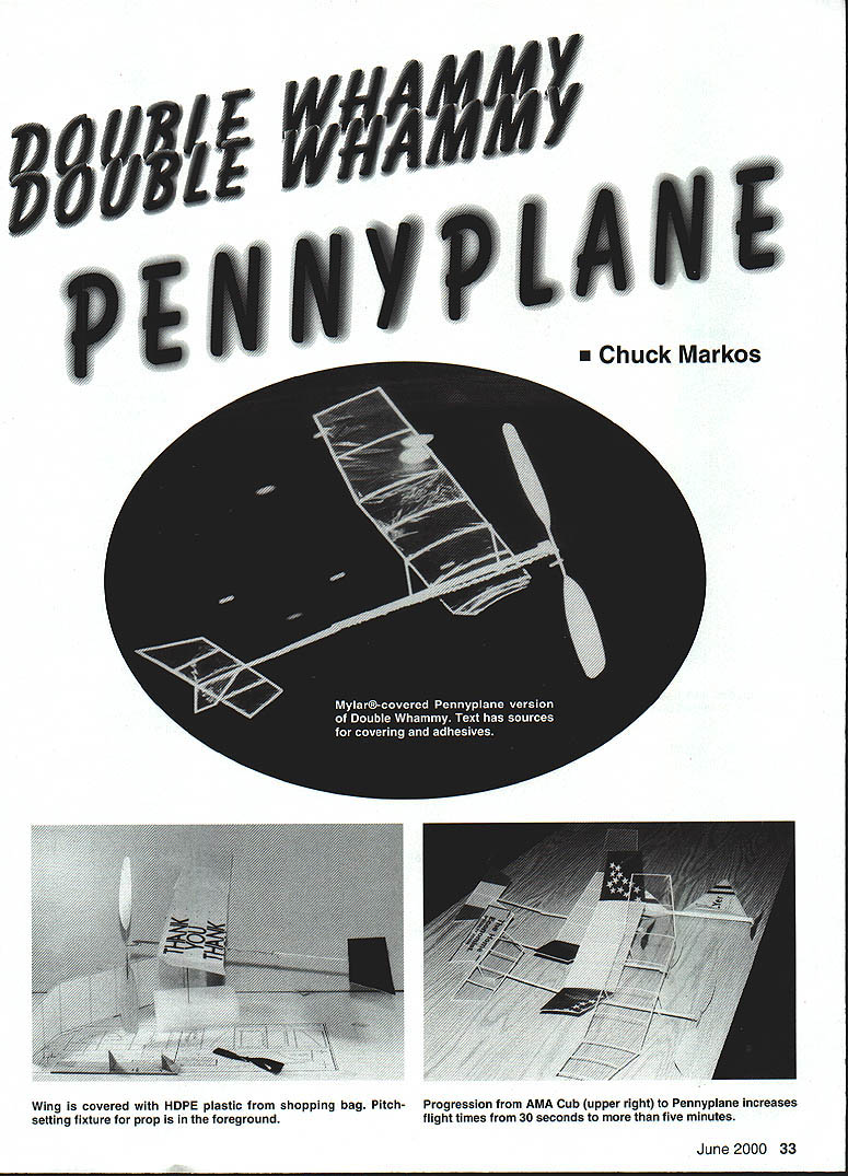
The model presented in this article is a serviceable Pennyplane (minimum weight = 3.1 grams or one 1970s penny) that can be made with materials and tools available to the non‑indoor specialist. It can provide flights of more than five minutes in a typical high‑school gym (26‑foot ceiling).
Just think what an accomplishment it is to go from an AMA Cub and 30‑second flights to an Indoor model capable of five minutes—in two easy steps!
NOW THAT YOU have mastered the basic Double Whammy construction and flying (November 1999 MA), you may be inspired to move to a higher level of performance using the same plans. The changes described in this article will allow you to easily double the flight times achieved with the basic model, even using the same 1/16 rubber motor that powered the plastic‑propeller‑driven model.
Three changes will be made:
- Substitution of a balsa propeller for plastic
- A cambered airfoil in place of the flat plate
- A lighter‑weight and less‑porous covering for the wing
Everything else from the basic model can come along for the ride. The changes are not strictly state‑of‑the‑art Indoor modeling, but are easy to accomplish using readily available materials and tools.
Propeller
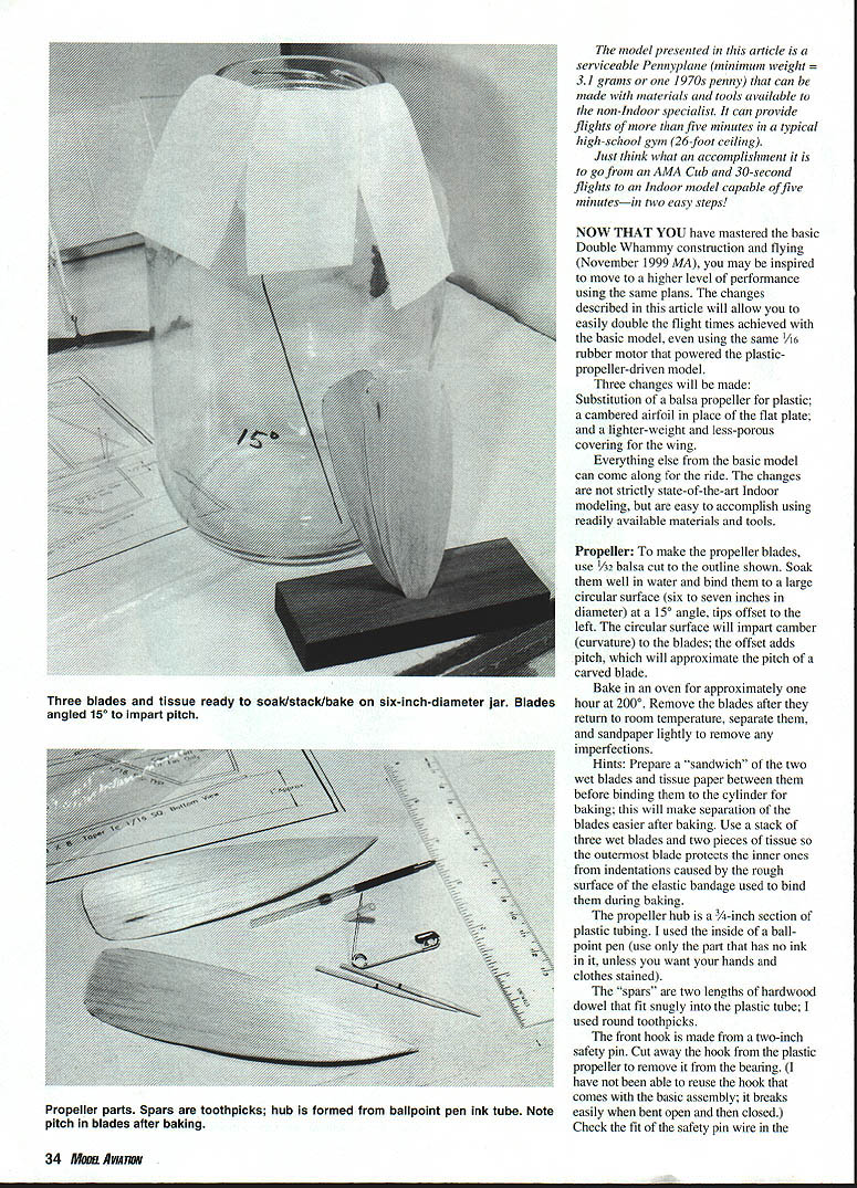
To make the propeller blades, use 3/32 balsa cut to the outline shown. Soak them well in water and bind them to a large circular surface (six to seven inches in diameter) at a 15° angle, tips offset to the left. The circular surface will impart camber (curvature) to the blades; the offset adds pitch, which will approximate the pitch of a carved blade.
Bake in an oven for approximately one hour at 200°F. Remove the blades after they return to room temperature, separate them, and sand lightly to remove any imperfections.
Hints:
- Prepare a "sandwich" of the two wet blades with tissue paper between them before binding them to the cylinder for baking; this will make separation of the blades easier after baking.
- Use a stack of three wet blades and two pieces of tissue so the outermost blade protects the inner ones from indentations caused by the rough surface of the elastic bandage used to bind them during baking.
The propeller hub is a 3/16‑inch section of plastic tubing. The inside of a ballpoint pen tube can be used (use only the part that has no ink in it).
The "spars" are two lengths of hardwood dowel that fit snugly into the plastic tube; round toothpicks are suitable.
The front hook is made from a two‑inch safety pin. Cut away the hook from the plastic propeller to remove it from the bearing. (The hook that comes with the basic assembly often breaks when bent open and closed and may not be reusable.) Check the fit of the safety pin wire in the bore of the hub; sand if necessary. Slip the two blades over the hub and join them at their roots with thin cyanoacrylate adhesive (Zap CA), then apply a small fillet of CA to the hub/blade junction on both sides. Balance the blades by removing a small amount of balsa from the heavier blade root.
Note: Part of the original scan was illegible. Please provide a higher‑resolution scan or an additional image of the lower‑right portion if you want a complete verbatim transcription of any missing sentences.
Make a hole through the plastic tube hub using the sharp point of the safety pin. Make sure the hole is orthogonal (centered) when the hub is spun on the shaft, so the completed prop will "track" properly (no wobble in the blades).
Glue the two hardwood dowels to the blades, leaving exactly one inch sticking out. The propeller is assembled on a pitch‑setting fixture, as described below.
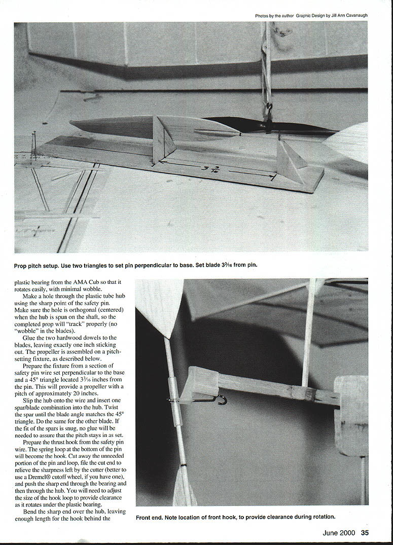
Prepare the fixture from a section of safety pin wire set perpendicular to the base and a 45° triangle located 3¾ inches from the pin. This will provide a propeller with a pitch of approximately 20 inches.
Slip the hub onto the wire and insert one spar/blade combination into the hub. Twist the spar until the blade angle matches the 45° triangle. Do the same for the other blade. If the fit of the spars is snug, no glue will be needed to assure that the pitch stays as set.
Prepare the thrust hook from the safety pin wire. The spring loop at the bottom of the pin will become the hook. Cut away the unneeded portion of the pin and loop, file the cut end to remove the sharpness left by the cutter (better to use a Dremel® cutoff wheel, if you have one), and push the sharp end through the bearing and then through the hub. You will need to adjust the size of the hook loop to provide clearance as it rotates under the plastic bearing.
Bend the sharp end over the hub, leaving enough length for the hook behind the plastic bearing to rotate freely. Note that the sharp end of the pin may be tempered to a different hardness than the rest of the wire. If so, it may break when you attempt to bend it. It is not necessary to keep the sharp end; you only need enough wire so that the hook clears the bearing.
The hook will probably not clear the bottom of the motorstick; however, adequate clearance can be achieved by moving the balsa scrap fill from the top of the motorstick to the bottom before replacing the bearing at the front.
Wing
Construct a new wing using 1/16 square balsa for the leading edge (LE) and trailing edge (TE) as in the original Double Whammy, but substitute sliced ribs for the 1/16 square cross‑pieces.
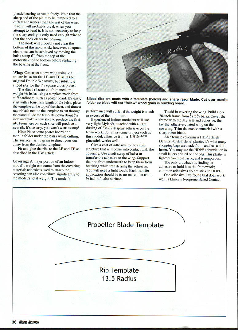
The sliced ribs are cut from medium‑weight 1/32 balsa using a template made from stiff cardboard, such as poster board. Start with a four‑inch length of 1/32 balsa, place the template at the top of the sheet, and draw a razor blade next to the template to cut through the wood. Slide the template down about 1/16 inch and make a new slice to produce the first rib. Each subsequent slice will produce a new rib.
Hint: Place some poster board or a manila folder under the balsa while cutting. The surface has no grain to direct your cut away from the desired template.
Fit and glue the ribs to the LE and TE as described in the Double Whammy article.
Covering
A major portion of an Indoor model's weight can come from the covering material; adhesives used to attach the covering can also contribute significantly to the model's total weight. The model's performance will suffer if its weight is much in excess of the minimum.
Experienced indoor modelers will use very light Mylar®, attached with a light dusting of 3M‑77® spray adhesive on the framework. For a first‑time project such as this model, adhesive from a UHListic™ glue stick works well.
Procedure with Mylar:
- Give a coat of adhesive to the center structure that will come into contact with the covering.
- Use a soft scrap of balsa to transfer the adhesive to the wing. Support the ribs from underneath to keep them from breaking while transferring the adhesive.
- Apply each transfer to no more than about 1/2 inch of balsa surface at a time.
- To aid in covering the wing, build a 6 × 20‑inch frame from 1/8 × 1/4 balsa. Cover the frame with the Mylar® and adhesive, then lay the adhesive‑coated wing on the covering. Trim the excess material with a sharp razor blade.
Alternate covering: HDPE (High Density PolyEthylene) plastic (common shopping bag material) has a dull luster and is lighter than most tissue, and is nonporous. The only drawback is finding an adhesive that sticks to HDPE. One adhesive that works well is Elmer's Neoprene Based Contact Cement, diluted with two parts water. Product numbers: E‑753 (three‑ounce bottles) and E‑751 (quart cans). Borden customer service can provide local retail outlets. Use a bit of foam from a "Beauty Wedge" as a disposable applicator. Place the HDPE covering over the adhesive‑treated wing and lightly press into place on the LE and TE. Wait about one hour before trimming the excess with a sharp razor blade.
The dihedral joints are glued and the wing posts are added as in the Double Whammy, with about 1/8‑inch skew, to force the wing into a twist when the posts are snugly fit into their sockets.
Sliced ribs are made with a template and a sharp razor blade. Cut over a manila folder so the blade will not "follow" the wood grain in the building board.
(Propeller blade and rib template drawings were included in the original article.)
Setup and Flying
Recheck the balance point of the fuselage‑propeller/bearing‑rubber motor combination. If it is not near the center of the wing, the sockets for the wing posts should be repositioned.
If the model doesn't gain sufficient altitude with the same rubber motor used for the plastic‑propeller version, it may be too heavy; the quick fix is to reduce the propeller's diameter by cutting away blade area at the tips.
If you have access to a rubber stripper, or know someone who does, a larger‑size motor can also be prepared. Tests showed that the Mylar®‑covered model made six‑minute flights easily with a loop of .070 Tan II rubber. The HDPE‑covered model, which is about 1/2 gram heavier, flew for about four minutes with the same motor (and did about 3 1/2 minutes with an .060 motor).
A weight of roughly 3.5 grams should be easily achievable with this design. The biggest weight reductions can be made by using lighter wood for the propeller and motor stick. Substitution of plastic covering on the tail surfaces will also help. Use of a lighter‑weight wire for the thrust hook will require some sort of fill for the hole in the bearing. The teflon tube from a CyA glue applicator has been used as fill to reduce the wire size to .015 from the .036 safety‑pin wire.
If you are fortunate enough to fly with experienced indoor modelers, inspect their models and you will find all sorts of weight‑reducing construction techniques and materials.
Chuck Markos 655 Carlisle Ave. Deerfield IL 60015
Source:
Lightweight Mylar®: Model Research Labs 25108 Marguerite #160 Mission Viejo CA 92692 www.modelresearchlabs.com Catalog $2 + SASE (55 cents postage)
Transcribed from original scans by AI. Minor OCR errors may remain.

