
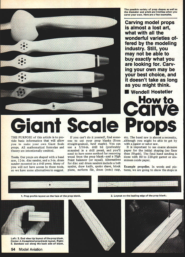
How to Carve Giant Scale Props
Wendell Hostetler
The purpose of this article is to provide basic information to allow you to make your own Giant Scale props. All mathematical formulas and theory are intentionally omitted.
Tools
- Primary tools used: band saw, 12-in. disc sander, 3-in. drum sander mounted in a drill press.
- Alternatives if you lack those tools: belt sander, draw knife, spoke shave, block plane, surform file, drum (rotary) rasp, jigsaw or saber saw (for cutting if no band saw).
- If you can't do the cutting yourself, have someone cut your prop blanks from straight-grained, kiln-dried, hard maple.
- Use a 5/16-in. drill bit (preferably in a drill press) for the center hole.
- You will need a method of removing wood from the blank and a High Point balancer (or equivalent) for balancing.
- Use coarse abrasive paper for initial shaping (no finer than 50-grit). Final hand sanding should be done with 80 to 220-grit garnet or aluminum oxide paper.
Example propeller (18 in. diameter, ~9 in. pitch)
This example prop works well on a .24 Kioritz engine. On 22–28 lb biplanes it should turn close to 8,000 rpm static (ground-unloaded), which is near the peak of the engine's horsepower curve.
- Cut the blank from straight-grained, kiln-dried, hard maple sized 3/4 x 1-5/8 x 18 in. Keep all angles at 90 degrees.
- Lay out the center lines, circle at the hub, and prop profile on the face of the blank. Mark lines on the leading edge to represent the face and back surfaces. Lay out 1/8-in.-wide lines on the end of the blank. Use the centerline for referencing the pattern.
- Drill a 5/16-in. hole (or a hole the size of your engine shaft) in the center of the prop blank. Use a center punch as a drilling guide and a drill press.
- Cut out the prop blank per the layout.
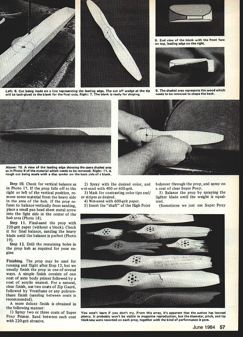
- Remove wood from the back surface as shown in the drawings. The removed area should come to within 1/8 in. of the top of the leading edge near the hub and taper thinner toward the tip. This allows shaping the leading edge to obtain approximately a Clark Y airfoil.
- Shape the wood on the face of the prop.
- Roughly check horizontal balance after each major wood removal. If the prop rotates to one side, imbalance is likely due to unequal shaping.
- Hand-sand the prop with abrasive wrapped around a wood block, starting with 80-grit and progressing to 220-grit. This removes irregularities left by power sanding.
- Carefully check horizontal balance. Sand lumps off the heavy side until both blades weigh the same.
- Check vertical balance. If the prop falls to one side vertically, remove material from the heavy side near the hub. If necessary, place a small pan-head sheet-metal screw in the light-side center-hub area to balance.
- Final-sand the prop with 220-grit paper on a block. Recheck balance and sand the heavy blade until balance is perfect.
- Drill the remaining hub holes required for your engine.
A prop may be used for running and flight after Step 12.
Finishing
- Simple finish: one coat of auto-body primer followed by a coat of acrylic enamel.
- Natural/clear finish: two coats of Zip-Guard followed by Verathane polyurethane; sand between coats.
- Deluxe finish (recommended process):
- Spray two or three coats of Super Poxy Primer. Sand between each coat with 220-grit abrasive.
- Spray desired color; wet-sand with 400- or 600-grit.
- Mask for contrasting color tips and/or stripes as desired.
- Wet-sand with 600-grit paper.
- Insert the shaft of the High Point balancer through the prop and spray one coat of clear Super Poxy.
- Balance the prop by spraying the lighter blade until weight is equalized.
After finishing, record diameter, pitch, tip thickness, and observed performance on each prop.
Familiarize Yourself With These Terms
- Face of prop: Surface facing you when standing in front of the aircraft.
- Back of prop: Surface viewed from inside the cabin or cockpit.
- Leading edge: Edge that leads as the prop rotates counter-clockwise (as viewed from in front of the aircraft).
- Trailing edge: Edge opposite the leading edge.
- Prop profile: General outline of the prop as viewed from the front.
- Prop hub: Center portion where the prop bolts are installed.
- Pitch degrees: Angle the blade slopes off a flat surface when laid flat on the back side of its hub; measured from leading edge to trailing edge.
- Pitch: The theoretical distance a propeller advances through the air in one revolution.
- Prop blade: Portion of the prop extending from the hub to the tip.
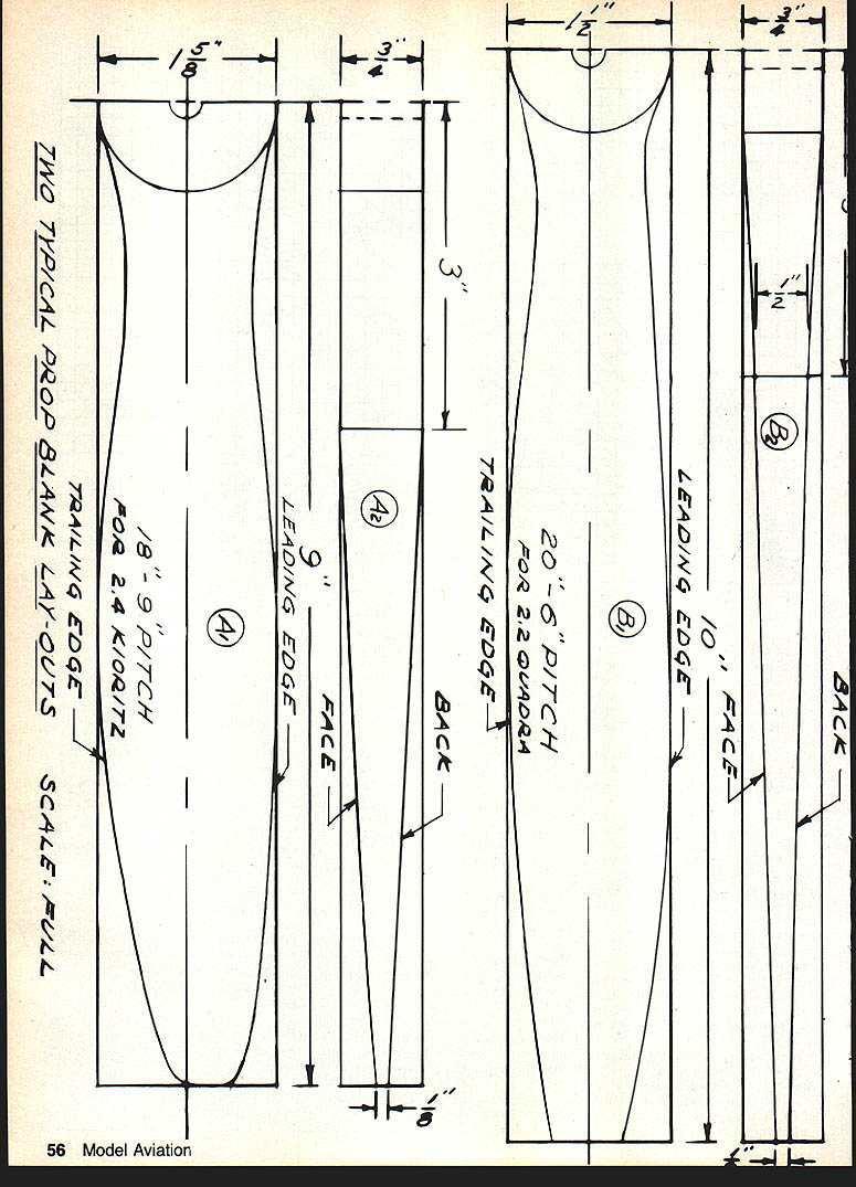
TWO TYPICAL PROP BLANK LAYOUTS
- 18" diameter — 9" pitch for .24 Kioritz
- Note layout includes leading edge, face, back, trailing edge, and 1/8-in. tip thickness. The 75% station for an 18-in. prop is 6.75 in.
- 20" diameter — 6" pitch for .22 O.S.
- Layout similar but sized for the appropriate diameter and pitch.
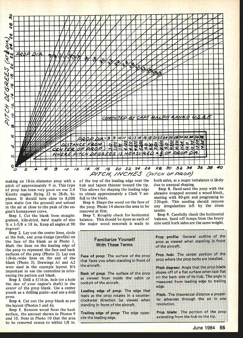
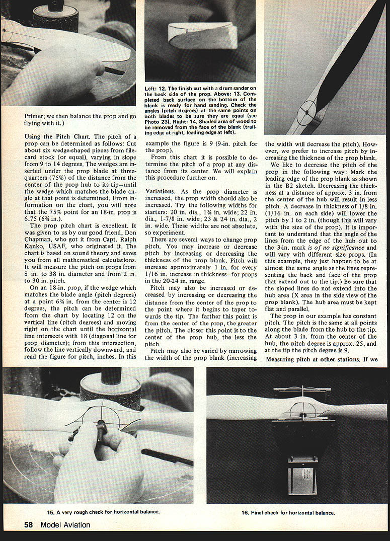
Using the Pitch Chart
- To determine pitch degrees visually: cut about six wedge-shaped pieces of card stock with slopes from about 9° to 14° (or a suitable range). Insert the wedges under the prop blade at 75% of the distance from hub center to tip until you find the wedge that matches the blade angle at that station.
- For an 18-in. prop, the 75% point is 6.75 in. If the matched wedge shows 12° at that point, use the pitch chart: locate 12° on the vertical, move right to intersect the diagonal line for 18-in. diameter, then read down to get the pitch in inches (example: 9 in.).
- The chart measures pitch for props 8 in. to 38 in. diameter and 2 in. to 30 in. pitch.
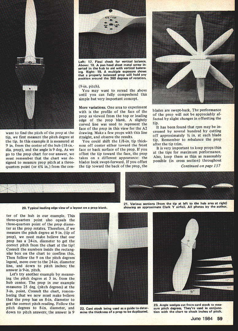
- You can determine pitch at any radius. For example, if you measure pitch degrees at 3 in. from the hub and read 25°, pretend the prop diameter is 8 in. (double the 3-in. station for comparison), find 25° versus 8 in. on the chart, and read the equivalent pitch (example yields about 9 in.).
Variations and Tips
- Increase prop width as diameter increases. Suggested starter widths:
- 20 in. dia. — 1-3/4 in. wide
- 22 in. dia. — 1-7/8 in. wide
- 23–24 in. dia. — 2 in. wide
These are not absolute—experiment.
- Change pitch by:
- Increasing or decreasing blank thickness: in the 20–24 in. range, pitch changes roughly 1 in. per 1/16 in. thickness change.
- Changing the distance from center to the point where the blade begins to taper toward the tip: moving this point farther out increases pitch.
- Changing blank width: narrowing increases pitch; increasing width decreases pitch.
- Preferred method: change pitch by altering blank thickness.
- To decrease pitch: reduce thickness at about 3 in. from the hub center (approximately 1/8 in. total reduction, 1/16 in. on each side, can lower pitch by 1–2 in., varies by size). Ensure sloped lines do not extend into the hub area; keep the hub flat and parallel.
- The example prop has nearly constant pitch from hub to tip: about 25° at 3 in. from center and about 9° at the tip.
- Face profile experiments: try straight vs. slightly curved face lines and observe results.
- Tip offset: moving the 1/8-in. tip thickness toward the face makes blades look swept-forward; toward the back makes them swept-back. Small offsets have minimal performance effect.
- Tip trimming: cutting about 1/8 in. off each blade tip can increase rpm by several hundred—rebalance after trimming.
- Keep props thin at the tips and as thin as practical throughout the blade for maximum performance.
You won't learn unless you try—record diameter, pitch, tip thickness, and performance for each prop you make to build experience.
Transcribed from original scans by AI. Minor OCR errors may remain.

