
If It Flies ...
Dean Pappas
That troublesome horizontal tornado from the propeller
Dean Pappas
IF IT FLIES, it probably has a propeller in front of it: part two. That's right, this is part two of a discussion about the many side effects of using a propeller to make flying thrust. This meandering response to a simple question is part and parcel of the "If It Flies ..." approach to things that fly.
Many different but related influences play together and dictate how our airplanes fly. And when we pull on any one thread, it may lead to finding out about the original question, as well as something else. It's all connected.
This whole investigation started with a question about the merits of a rear-exhaust engine vs. a side-exhaust engine-and-muffler combination. Thanks again, Mert! The entire subject of care and feeding of tuned-exhaust systems, which are most often used on rear-exhaust engines, is still tucked away in a corner. We'll have a long discussion about that another day.
What we did cover was the effect of an asymmetric muffler and cylinder mass. To recap, the typical 60-size sport aircraft with an upright engine and standard muffler has a side-to-side imbalance that works out to the equivalent of maybe three-eighths of an ounce placed out on a wingtip.
If the model is flown and trimmed with this imbalance, opposing (left) aileron trim will be necessary for straight and level flight. As the airspeed changes, the effect of the aileron trim will change, but the effect of the weight will not. That is far from ideal, and it adds to the flying workload any time the airplane is slowed during takeoff or landing.
A small lump of weight will mostly fix the problem. The word "mostly" represents the loose end we will pull at, someday, to start a discussion about how to trim an airplane to do nice, straight loops.
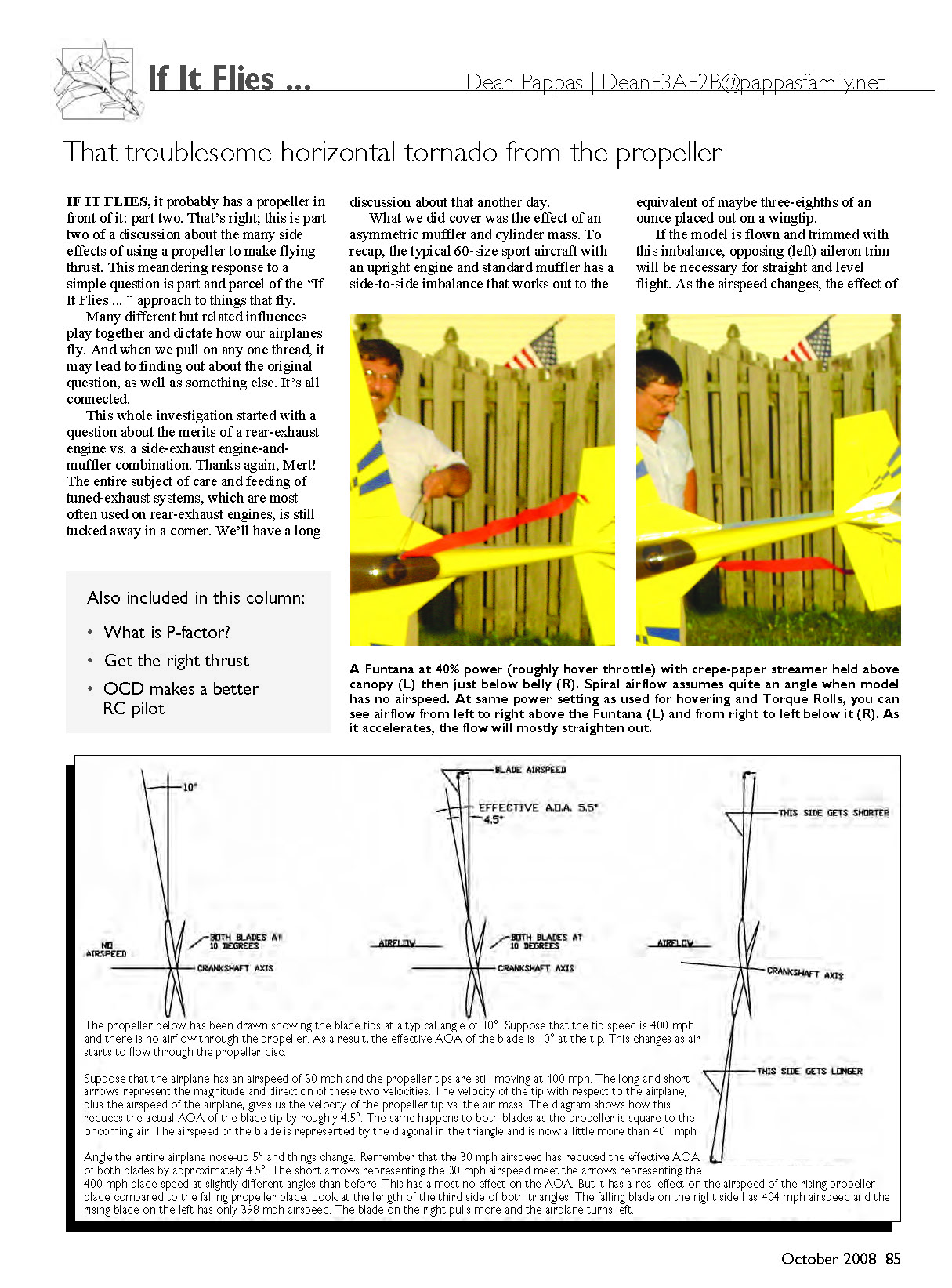
Spiral Airflow—That Troublesome Horizontal Tornado: The spiral airflow that swirls along the model's length destroys any hope of having a symmetric airplane. A normal "right-hand" propeller's spiral airflow strikes the right side of whatever "chin" the airplane has and the left side of the fin and rudder. This is why your aircraft yaws left on takeoff and requires right thrust to compensate.
This tendency to veer to the left when power is added is typically lumped under the term "torque"; as in, "I pushed the throttle up and she torqued over on me!" There are several components to this torque. They are:
- The spiral airflow pushing the tail to the right.
- Pure torque reaction.
- The opposite rolling effect of spiral airflow on the wings and stabilizer.
- The tough to explain but usually unimportant P-factor.
As I wrote in the August issue, the explanation in the preceding list is why the model needs right thrust. Items 2-4 add up to a fraction of the influence caused by spiral airflow.
Let's work backward and talk about P-factor first. Contrary to popular belief, it has nothing to do with the distance between highway rest stops while driving to a model fly-in. It is a movement of the center of thrust to the right of the crankshaft as the propeller disc is angled away from perpendicular to the incoming airflow.
As the center of thrust moves to the right, a yaw to the left is produced. P-factor causes this yawing force to the left only when the airplane is moving fairly fast with the nose high.
When the nose is high, the aircraft is moving through the air, and the propeller is turning, the propeller blade on the right side of the model is moving downward and forward compared to the propeller blade on the left. Therefore, the descending blade is taking a bigger bite of air. It is operating at a higher angle of attack (AOA) to the airflow, compared to the rising blade on the left.
How much more lift does it make? There's the real question. Your typical foot-long propeller turning in the neighborhood of 12,000 rpm has a blade-tip speed that just exceeds the speed of sound. The propeller tip is moving at roughly 425 mph, compared to the nose of the aircraft.
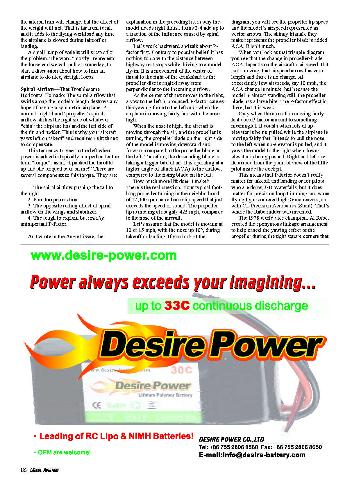
Suppose that the tip speed is 400 mph and there is no airflow through the propeller. As a result, the effective AOA of the blade is 10° at the tip. This changes as air starts to flow through the propeller disc.
Suppose that the airplane has an airspeed of 30 mph and the propeller tips are still moving at 400 mph. The long and short arrows represent the magnitude and direction of these two velocities. The velocity of the tip with respect to the airplane, plus the airspeed of the airplane, gives us the velocity of the propeller tip vs. the air mass. The diagram shows how this reduces the actual AOA of the blade tip by roughly 4.5°. The same happens to both blades as the propeller is square to the oncoming air. The airspeed of the blade is represented by the diagonal in the triangle and is now a little more than 401 mph.
Angle the entire airplane nose-up 5° and things change. Remember that the 30 mph airspeed has reduced the effective AOA of both blades by approximately 4.5°. The short arrows representing the 30 mph airspeed meet the arrows representing the 400 mph blade speed at slightly different angles than before. This has almost no effect on the AOA. But it has a real effect on the airspeed of the rising propeller blade compared to the falling propeller blade. Look at the length of the third side of both triangles. The falling blade on the right side has 404 mph airspeed and the rising blade on the left has only 398 mph airspeed. The blade on the right pulls more and the airplane turns left.
When you look at that triangle diagram, you see that the change in propeller-blade AOA depends on the aircraft's airspeed. If it isn't moving, that airspeed arrow has zero length and there is no change. At exceedingly low airspeeds, say 10 mph, the AOA change is minute, but because the model is almost standing still, the propeller blade has a large bite. The P-factor effect is there, but it is weak.
Only when the aircraft is moving fairly fast does P-factor amount to something meaningful. It counts when lots of up-elevator is being pulled while the airplane is moving fairly fast. It tends to pull the nose to the left when up-elevator is pulled, and it yaws the model to the right when down-elevator is being pushed. Right and left are described from the point of view of the little pilot inside the cockpit.
This means that P-factor doesn't really matter for takeoff and landing or for pilots who are doing 3-D Waterfalls, but it does matter for precision loop trimming and when flying tight-cornered high-G maneuvers, as with CL Precision Aerobatics (Stunt). That's where the Rabe rudder was invented.
The 1978 world vice champion, Al Rabe, created the eponymous linkage arrangement to help cancel the yawing effect of the propeller during the tight square corners that are common in the Stunt maneuver schedule. These high-G corners involve high AOA at maneuvering speed; and that is, after all, the necessary condition for P-factor to happen.
If you type "Rabe rudder" into the Google Internet search engine, you'll probably get quite a tour through the CL fora (not forums!) on the subject.
Let's look at items 2 and 3 in the list. The pure torque reaction comes from Newton's third law of motion. For every action, there is an equal and opposite reaction.
As the propeller twists the air into a horizontal tornado, there is a torque around the crankshaft twisting the airplane as if left aileron had been applied. This same airflow strikes the wing and tail as it flows along the aircraft, and these "feathers" tend to straighten that spiral tornado, leading to another torque to the right.
Hmmm. Do they cancel out? It depends on the airspeed. While the model is sitting still, they do not, and that's how models do Torque Rolls without aileron input. With increasing airspeed, they come closer to canceling each other out. This is especially true because the spiral airflow also tends to straighten out as the airspeed goes up. So two plus three almost equals zero.
Now we go back to the spiral airflow. It strikes the right side of whatever "chin" the airplane has, and it strikes the left side of the fin and rudder.
The center of the fin and rudder area is normally centered above the aircraft's thrustline, so the net action is that the tail is pushed to the right and the nose is pushed to the left. That's why your model yaws left on takeoff and requires right thrust to compensate.
Because the spiral airflow creates this yaw to the left, we add right thrust to the engine mount. So all we should have to do is find the proper right-thrust angle. Right? For most cases, the answer is yes. For others, some sort of compromise is needed. Why?
The amount of spiral airflow depends on the horsepower the engine is producing, the propeller's pitch and diameter, and the model's airspeed. The faster it flies, the less the airflow spirals, even if the engine is making the same horsepower. The slower the airplane flies, the worse the spiral airflow, and the yaw to the left, will be. The result is that the right-thrust angle will be a compromise.
For aircraft that climb at a steady, acceptably high airspeed, there is a right-thrust angle that works with little or no compromise. What does "acceptably high airspeed" mean? Acceptable to you.
For a sport or training model, it means that when you raise the nose to the climb angle you want to use, the airspeed stays high enough for solid control without eventually slowing. If the airplane does slow down, and the controls become mushy, the climb angle is too steep for the horsepower you have. You will have to reduce your angle of climb.
Once you have figured that out, the way to check whether or not you have enough right thrust is to trim the aircraft to fly straight and level at whatever throttle setting you normally use for cruise and then go to full throttle and establish that same climb angle. If the model wanders off to the left, you need to add more right thrust. If it wanders off to the right, remove a bit.
You really need to do this test straight into the wind and in smooth-air or calm conditions. Such dream air tends to materialize at sunset. Besides, the sunset looks so good at the flying field!
Right thrust is often a compromise for the 3-D and serious aerobatics types, because the maximum climb angle for them is vertical. That's right; it's straight up like a rocket. If you have the horsepower-to-weight ratio of an Atlas booster, all is well. The sustained-vertical-climb airspeed will be high enough that you will probably end up with less than 3° of right thrust to maintain a straight vertical climb.
You start from the same condition as with the sport airplane: trimmed for straight and level flight at cruise power. If, on the other hand, your aircraft continues to slow in a vertical climb, no amount of right thrust will work without creating all kinds of other problems during the rest of your flight.
For a more complete description of how to test for and adjust right thrust, read the "Trimming From the Ground Up" series at MA's Sport Aviator online magazine. This article was also published in MA. The pertinent portion of the feature is in the middle one. See the source list at the end of this column for Web addresses.
RC Aerobatics Flying and Other Forms of Obsessive-Compulsive Disorder (OCD): The RC Aerobatics (Pattern) pilots of yore were, in many ways, no different from those of today. They are obsessive-compulsive about trimming their airplanes to help give them a competitive advantage.
This meant adjusting so that the model would track straight through three consecutive Inside Loops and three consecutive Outside Loops. That greatly reduced the workload in maybe half of the maneuvers on the schedule if you were patient and tested carefully on nice, calm evenings. Still, the unbalanced weight and drag of the muffler or side-mounted engine made perfect trim a rarity.
Along came tuned-pipe exhaust systems in the mid-1970s. Then instead of a muffler that was maybe 6 inches long, we had two-piece exhaust systems that were maybe 25 inches long from front to back.
Not only did they weigh a bit more than a simple muffler, but they created more aerodynamic drag and all kinds of aerodynamic forces as the model's attitude changed during maneuvers. All this bother was justified by the 25%-30% increase in usable horsepower that the tuned pipe produced.
The solution was to put a rear-exhaust engine in the model, either upright or inverted. The Pattern pilots had to get a manufacturer to create a 60-size rear-exhaust engine. The CL Speed event had used rear-exhaust engines for years, for drag reduction, but in different sizes than those needed by the Pattern fliers.
Rossi and Webra were the first to introduce rear-exhaust Pattern .60s, and most other manufacturers quickly followed suit. This piped, rear-exhaust format lends itself to fully cowled-in power plants that cause no mass or drag imbalances. That explains how so many Pattern designs have evolved the way they have.
Do let us know what you'd like to read about. Until next time we get together, have fun and take care. MA
Sources:
- "Trimming From the Ground Up":
www.masportaviator.com/ah.asp?ID=141&Index=0 www.masportaviator.com/ah.asp?ID=142&Index=0 www.masportaviator.com/ah.asp?ID=144&Index=0
Transcribed from original scans by AI. Minor OCR errors may remain.

