
What is the aerodynamic center, and what does it mean?
Dean Pappas | [email protected]
Back when I was maybe 17 years old, there was a construction article in the old American Aircraft Modeler (AAM) magazine for an RC Aerobatics (Pattern) model called the "Warlock." Hello out there, Jim Wilmot. If you are reading this, it may please you to know that your novel design and amusing article are remembered.
It was a radical design (even today the Warlock would be viewed as radical), with tandem retractable landing gear and wing outriggers, as on a U-2 spyplane; aggressive angular lines; and, most intriguingly to me, an all-flying horizontal tail or stabilator.
This was cool, not only because all of the latest supersonic fighter jets were being designed with all-flying tails, but also because all the talk I'd ever heard at the local flying field about stabilators was that they were tricky. Put the pivot in the wrong spot, and they would either flutter off the airplane at speed or overload the servo and cause a crash.
Wonder of wonders, here were shrunk-down plans in the magazine that showed a working stabilator design, complete with the correct pivot tube location and construction details. I would appropriate this design element and use it in an airplane I had been contemplating for a while.
The wing was swept an inch or two at the trailing edge, with a tip chord something near 70% of the root chord, and the symmetric airfoil was borrowed from the late Pappy deBolt's Live Wire Sonic Cruiser design. My dad had built and flown the daylights out of one of these when I was 8 or 9 years old. After its demise, I had made a CL flying wing from the surviving outer one-third of both wing panels. It flew pretty well, as I remember. The airfoil was an NACA 64012, and further homage had been paid to Pappy when Art Schroeder (long-time editor of Model Airplane News magazine) used it in his popular and successful Eyeball design series.
The fuselage moment arms (the length from propeller to wing aerodynamic center and from the wing's aerodynamic center to the stabilator pivot) were lifted from yet another popular Pattern aircraft of the day, and the fuselage had the popular, at the time, fishlike profile. The triangular fin and rudder had a dorsal fin that ran all the way up to the canopy in a stylish curve, because I liked how Dennis Donohue's El Tigre looked. The airplane was never properly named and oh, how I wish I had a picture of it.
It was more an exercise in styling than aerodynamics, painted in gold and bright-red automotive lacquer. An O.S. .60 Blackhead provided the go, a World Engines Expert-series radio made it behave, and on the ground it sat on Rhom-Air retracts.
It flew great, as I remember, and even through the rose-colored lenses of nostalgia for my youth, I can accurately say that it was another 10 years before I was successful in designing anything that flew better.
Fast-forward to just a few months ago, when I was thinking back to the unnamed red-and-gold beast. In what can only be described as one of those serendipitous connections, I remembered that the Warlock construction article was published in the same issue of AAM as the CL Stunt (Precision Aerobatics) Sweet-Pea that my buddy, Dennis Adamisin, designed. (AAM was the predecessor to MA as the AMA’s house organ.)
Surely Dennis would have an old copy of the issue with his design in it. One enjoyable phone call later, a scanned version of the old article showed up in my e-mail. Thanks, compadre.
There it was: the stabilator design that got the ball rolling in the first place. Armed with just a bit more understanding than I had as a teenager, I carefully measured the stabilator plan, reproduced it in CAD, and did the calculations to see if the Warlock conformed to the usual rule for stabilator pivot placement.
Sure enough, it did: the pivot was right on the stabilator’s aerodynamic center (AC). Maybe that’s why I never had a bit of trouble with the elevator control on the old beast, despite the earth-moving 45 ounce-inches of torque that the World S-4 servo provided.
The airplane eventually died, when I forgot to extend the transmitter antenna before takeoff. (It’s always pilot error.) I lost control of the model immediately after doing the prettiest 8-point roll I had ever done.
It crashed through a thicket of saplings that strained the mechanical and radio bits from the lighter balsa bits like water from spaghetti in a colander. It took a lot of help from friends to find the crash site, too.
What is the AC, and what does it mean?
That is this month’s subject, and it is a lead-in to a discussion about why moving the CG (also called the balance point) forward or aft changes an airplane’s flying characteristics, making it more or less stable.
The textbook definition is simple enough, but, as with most technical language, very few words say a lot. The aerodynamic center (AC) of an airfoil, moving through the air, is the point at which the pitching moment for the airfoil does not vary with lift coefficient or angle of attack (AOA). Remember that “moment” is another word for “torque.”
Let’s decipher this. Every airfoil has what is called a zero-lift AOA. For the popular flat-plate airfoil and for symmetrical airfoils, the zero-lift angle is the same as the chord line for the airfoil. That makes sense, doesn’t it?
For semisymmetrical airfoils, flat-bottom airfoils, and undercambered airfoils, the zero-lift angle happens when the chord line is at a small nose-down angle compared to the oncoming air. It is simple to estimate the zero-lift angle for a large variety of airfoils, and we will revisit this some day (probably when I write about propeller pitch angles).
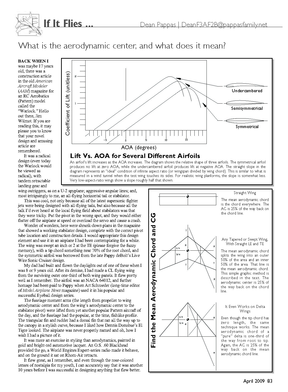
Starting from the zero-lift angle, the lift that an airfoil produces increases as the AOA increases. If you were to graph that change in lift versus AOA, you would get a straight line (over a moderate AOA range).
Lift versus AOA for several different airfoils:
- An airfoil’s lift increases as the AOA increases.
- A symmetrical airfoil produces no lift at zero AOA.
- An undercambered airfoil produces lift at negative AOA.
- The straight slope in an idealized diagram represents the condition of infinite aspect ratio; for realistic wings the slope is somewhat less, and very low-aspect-ratio wings show a slope roughly half as steep.
When any airfoil, including a flat plate, is driven through the air with a positive AOA, the oncoming air stagnates and "splits" at a point below (and maybe slightly behind) the front of the airfoil. The air that flows around the top of the leading edge speeds up a great deal. In fact, the fastest airflow over an airfoil is directly behind the leading edge on the top side.
Remember Bernoulli? The principle says that the air pressure on that part of the airfoil will be the lowest, and it will gradually increase toward the trailing edge. Also, the highest pressure is immediately behind the leading edge on the bottom side, quickly decreasing as the air flows toward the trailing edge.
Take a moment to play with the FoilSim Java program on the NASA web site (see the "Sources" listing for the address). Select the "Shape/Angle" menu button and watch the pressure distribution plot change as you fiddle with the AOA slider.
The trick to reading the pressure profile diagram is that the bottom line corresponds to the pressure on the top side of the airfoil, and the upper line, showing higher pressures, corresponds to the bottom of the airfoil. In the simulator the lines are shown as different colors, and it takes a while to pick them apart.
The result of the shifting shape of this pressure distribution is that if you pick a point close to one-quarter of the way back on the chord line, something fascinating happens. The difference between top and bottom pressures all along the chord line, multiplied by the lever arm away from that one-quarter chord point, would add up to a nose-down torque around the fulcrum at the one-quarter chord point.
The fascinating thing is that if you pick the one-quarter chord point as the fulcrum for this seesaw, the torque does not change with AOA until close to stall. It is almost natural, at this point, to say that the wing's lift acts upward through this aerodynamic center. This is because, as you look at changes in lift as the AOA is increased, you don't have to worry about changes in the pitching torque exerted by the wing. It simplifies the way we think about the wing's lifting characteristics.
This is what the definition of the AC really means. In the case of flat plates and symmetrical airfoils, that near-constant torque is zero. For semisymmetrical wings, there is a slight nose-down torque, and for flat-bottomed and undercambered wings, the torque is even stronger.
That's why the pivot point for the stabilator on the Warlock was placed one-quarter of the way back on the average chord of a symmetrical airfoil. The control forces on the elevator servo would be at a minimum.
If you don't think that the control forces needed to move a model airplane's control surfaces could be all that large, look at "The Great Rudder Experiment" performed some time ago by my friends Ron Ellis and Mike Whalley. You can find this excellent piece described epic-style on the Internet (see the "Sources" list). I highly recommend it.
Again, for most airfoils used on our models, the AC is right at the one-quarter chord point; that is, one-quarter of the way back from the leading edge. This is easy to figure out with a constant-chord, or "Hershey's-bar," wing. How do you figure out where it is on a swept wing? How about tapered? What about elliptical and other complicated wing shapes?
I'll start on that topic, but I won't finish it until the next time we get together. To begin with, instead of referring to the one-quarter point of the wing chord, we should start referring to one-quarter of the mean aerodynamic chord. The word "mean" in this instance is used in the same way as it is in statistics; it means average, not nasty. It is hard to prove this next statement, but here goes.
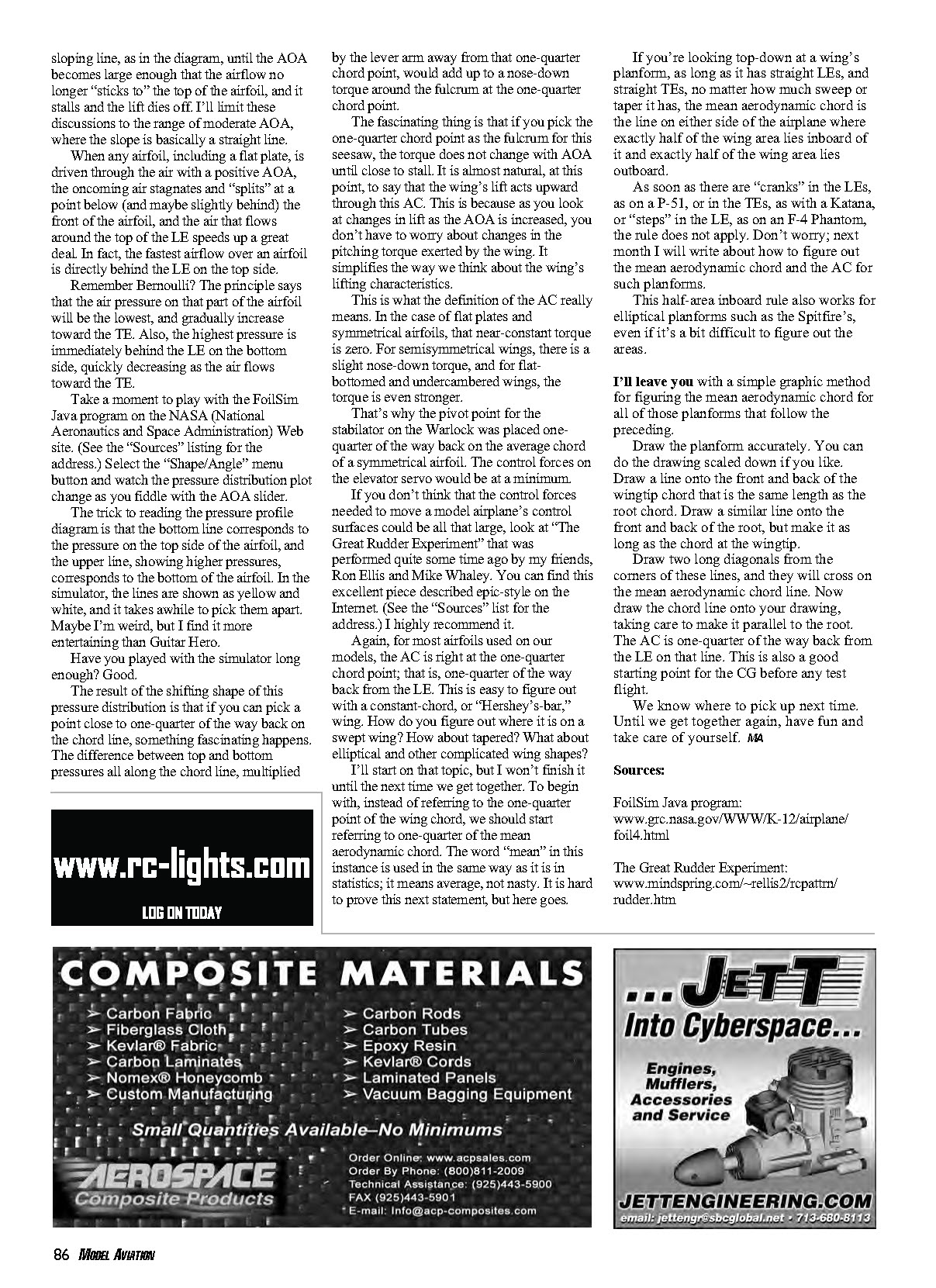
If you're looking top-down at a wing's planform, as long as it has straight leading edges and straight trailing edges, no matter how much sweep or taper it has, the mean aerodynamic chord is the line on either side of the airplane where exactly half of the wing area lies inboard of it and exactly half of the wing area lies outboard.
As soon as there are "cranks" in the leading edges, as on a P-51, or in the trailing edges, as with a Katana, or "steps" in the leading edge, as on an F-4 Phantom, the rule does not apply. Don't worry; next month I will write about how to figure out the mean aerodynamic chord and the AC for such planforms.
This half-area inboard rule also works for elliptical planforms such as the Spitfire's, even if it's a bit difficult to figure out the areas.
I'll leave you with a simple graphic method for figuring the mean aerodynamic chord for all of those planforms that follow the preceding.
- Draw the planform accurately. You can do the drawing scaled down if you like.
- Draw a line onto the front and back of the wingtip chord that is the same length as the root chord.
- Draw a similar line onto the front and back of the root, but make it as long as the chord at the wingtip.
- Draw two long diagonals from the corners of these lines; they will cross on the mean aerodynamic chord line.
- Now draw the chord line onto your drawing, taking care to make it parallel to the root. The aerodynamic center is one-quarter of the way back from the leading edge on that line. This is also a good starting point for the CG before any test flight.
We know where to pick up next time. Until we get together again, have fun and take care of yourself.
MA
Sources
- FoilSim Java program: www.grc.nasa.gov/WWW/K-12/airplane/foil4.html
- The Great Rudder Experiment: www.mindspring.com/~rellis2/rcpattn/rudder.htm
Transcribed from original scans by AI. Minor OCR errors may remain.

