
Mustang
By Pat Johnston
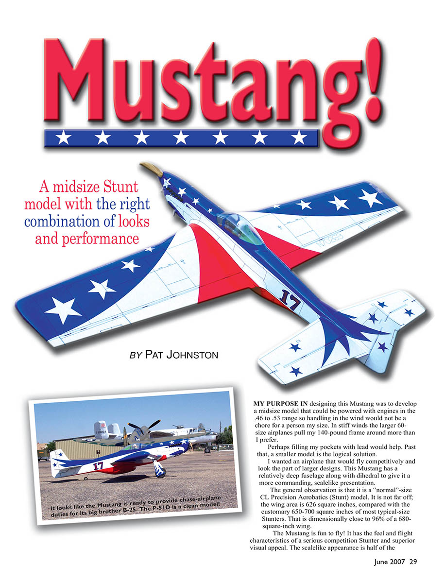
My purpose in designing this Mustang was to develop a midsize model that could be powered with engines in the .46 to .53 range so handling in the wind would not be a chore for a person my size. In stiff winds the larger 60-size airplanes pull my 140-pound frame around more than I prefer. Perhaps filling my pockets with lead would help. Past that, a smaller model is the logical solution.
I wanted an airplane that would fly competitively and look the part of larger designs. This Mustang has a relatively deep fuselage along with dihedral to give it a more commanding, scalelike presentation.
The general observation is that it is a "normal"-size CL Precision Aerobatics (Stunt) model. It is not far off; the wing area is 626 square inches, compared with the customary 650–700 square inches of most typical-size Stunters. That is dimensionally close to 96% of a 680-square-inch wing.
The Mustang is fun to fly! It has the feel and flight characteristics of a serious competition Stunter and superior visual appeal. The scalelike appearance is half of the equation and the color and trim scheme are the other part.
An unplanned additional component was the Magnum .53 engine and a tongue muffler. The flight judges have commented that the sound just comes out "Mustang." The .53 is a Leonard Neumann (of Stuka Stunt Works) modified engine swinging a wood 13 x 4.5 propeller at 8,500 rpm. The sound is pleasing and appropriate for the model. The Magnum .53 is out of production, and I have replaced it with a clone engine — the ASP .53 — which Leonard still sells.
The genesis of the paint scheme came from discussions my friend Jack Pitcher and I had while observing Paul Walker's colorful Mustang Stunter awhile back. Jack has a terrific-looking Stunter he has flown for years he calls the Centennial. The workmanship and finish are top-notch, but the model is painted mostly blue. The result is that the Centennial earns fewer appearance points than a flashier aircraft. Jack asserts that the airplane needs to be "flashy" to score well, and blue is not.
As I looked at Paul's big Mustang I envisioned a similar paint scheme with the American eagle morphed onto the side. Al Rabe used an eagle on one of his Bearcats from the late 1960s, and it was a striking trim scheme.
I also wanted to use a bright blue and red. Brodak Manufacturing sells a line of dope with a selection of colors that includes "Miss Ashley Red" and "Miami Blue." Both were just what I was looking for.
The Mustang is my third model to use this scheme. The first was my big Bearcat II, followed by a classic Al Rabe Bearcat. Both received high appearance points, and the judges always gave them strong flight scores. With this experience I decided not to deviate from this established theme.
For anyone who wants to do this trim scheme, I have drawn it on AutoCAD and will be happy to send it out. I enlisted a sign shop to cut the myriad stars with a low-tack vinyl masking material. That worked out beautifully and saved many hours of cutting stars by hand from frisket paper and then dealing with removing that frisket paper. Making 36 stars is a lot of work, and the vinyl masking is worth every penny.
Windy Urtnowski provided his cast epoxy-resin exhaust stacks, which give the nose a nice touch of realism. He recommends hollowing out the stacks to create the appearance of actual exhaust openings. It does look very good that way.
I resisted the temptation to airbrush smoke residue out the exhaust stacks and down the side of the model. It looks great on warbirds, but this Mustang is representative of a Reno Air Racing airplane; the pit crew would not allow its jewel to show smudges down the sides. Constant cleaning and a fresh wax job would be more like the real thing.
I made the ink lines with a 2.5-point-size Rapidograph ink pen. I prefer a slightly bolder line weight than from a pen in the 1-point-width category. As in Stand-Off Scale the panel lines need to be visible, and the 2.5-point-size pen is almost perfect.
The idea is to create the illusion and look of the Mustang and make people believe it is one, even though it's not scale. I am pleased by how well this design accomplishes that goal.
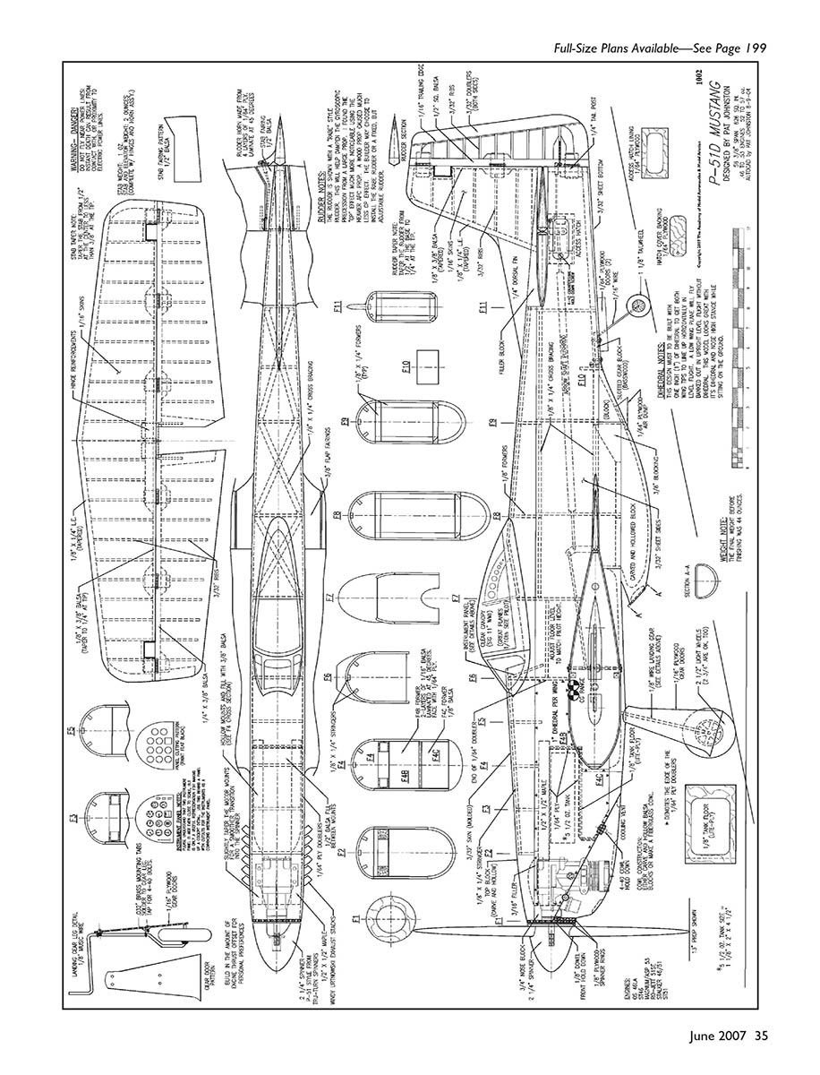
Construction overview
The Mustang's construction methods are relatively normal with a few exceptions. The most obvious deviation is the double taper in the wing to make the center wing bays that define the P-51 "D" model wing. These are not tough to frame up, especially when using the double-sheet leading edge (LE) component made from 1/8-inch balsa.
The 1/8-inch LE strips are overlapped at the intersection to produce an integral joint with no discernible weaknesses. A double-layer LE is not subject to the angular demands of a piece of 1/4-inch square LE stock, allowing a more versatile LE shape.
Don't overlook installing shear webs, which connect both spars, and the webs at the front edge of the trailing-edge (TE) sheeting. It is amazing how much this does to stiffen a wing against warps. The shear webs must be installed with the wing in the fixture to ensure that the wing remains true.
The relatively short nose demands that the tank compartment be set back into the wing an inch. Don't forget to cut the fuselage sides with the tank setback tabs in place. I forgot this on my second model and had to splice the tabs on.
The nose plywood doublers are 1/64-inch plywood. I find that to be plenty strong.
Many times we partake in gross overkill when it comes to "normal" construction methods. My philosophy is that until we find an area that presents a noticeable weakness, the design is usually overbuilt. Building the model light to begin with demands less intense structure.
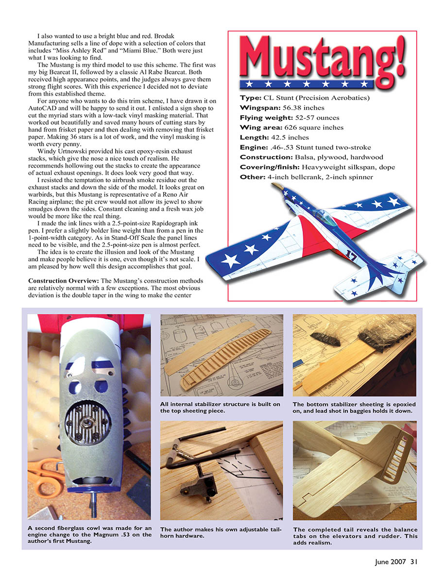
The tail surfaces are built up. The rudder is ribbed and covered with silkspan, which shows off the structure nicely. I usually do that to the elevator too, but the Mustang did not have fabric-covered elevators.
The ribs are placed at 1-inch intervals to prevent any noticeable sagging of the 1/16-inch balsa skins. This is working well; the tail surfaces have the look of being shaped from solid sheet stock but retain their lightweight qualities. The stabilizer is 1/2-inch thick at the center and tapers to less than 3/8 inch at the tip, which keeps the "look" from being too bulky.
Construction
Start this project by procuring a good supply of light balsa. That is tough to do locally here in Idaho, so I order from Lone Star Balsa. Specify the 6-pound stock. Most of the sheets are in the 5- to 7-pound range.
If you do not have a good scale, buy one! Stationery stores carry "letter scales" that cost less than $2 and will weigh balsa as heavy as 3 ounces. These scales are calibrated in ounces and grams.
A good 16-ounce scale is handy for measuring the weight of all the individual components. Wal-Mart carries a nice 16-ounce scale with a dial face for a reasonable price. A quality modeler must watch every gram that goes into an airplane.
The first priority is to decide which engine to install. We are in an era in which the selection of world-class Stunt engines has never been better. My first Mustang has the Neumann-modified Magnum .53 — an excellent engine. The all-up weight is 10.7 ounces, making it perfect for this model.
Other choices for power include:
- RO-Jett .51 SE (side exhaust)
- O.S. .46 LA
- SuperTigre .46 (if you still have one around)
- SuperTigre .51
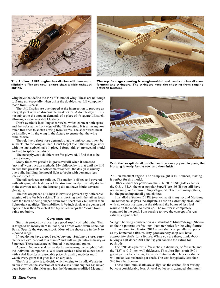
- Stalker .51 RE (rear exhaust), which I installed in my second Mustang — the rear exhaust gives the airplane's nose an extremely clean look with no exhaust system out the side and the bonus of less fuel residue on the model to clean up. The muffler is completely contained in the cowl.
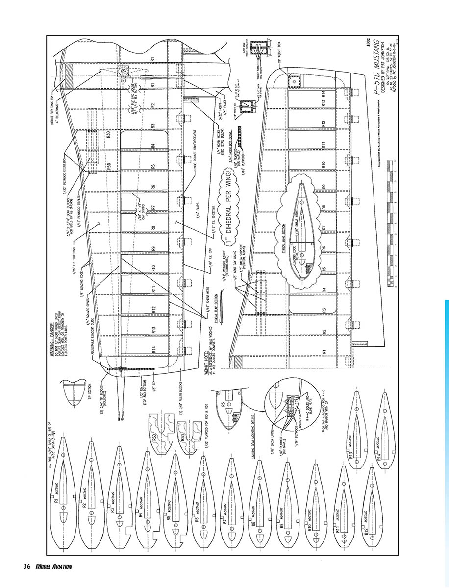
Wing
- The wing construction is a standard "D-tube" design. Shown on the rib patterns are 5/16-inch-diameter holes for the wing fixture.
- I have used two Easton 2013 arrow shafts on parallel supports as my homemade fixture. Any good archery shop will have appropriate shafts for a fixture. While you are there, think about buying a half dozen 2013 shafts; you can use the extras for pushrods.
- The "20" designation is 20/64 inches in diameter, or 5/16 inch, and the "13" is .013-inch wall thickness. This ultra-light shaft (0.9 grains per inch) is the right size for fixture rods. The extra shafts will make two pushrods per shaft. The cost is typically less than $20 for a half dozen.
- These aluminum shafts are as light as the carbon-fiber variety but cost considerably less. A local outlet sells extruded aluminum tubing at a cheap price. Most model shops carry a selection of the various sizes.
- When building the wing, be sure to install the shear webbing at the spars. I cannot overemphasize how important this is to the integrity of the wing. Use glue fillets at the spar joints and where the ribs meet the spars.
- The TE sheeting is 1/16-inch balsa. Pre-bend the sheeting by wetting it and forming it over a template. Glue the sheeting in place with thin CA or aliphatic resin, and sand smooth after the glue cures.
- The ailerons are built up with 1/4-inch balsa ribs and 1/16-inch balsa skins. Hinge with piano wire or commercial hinges; I prefer small hinges glued in with epoxy.
Fuselage
- The fuselage sides are 3/32-inch balsa. Build the fuselage over the plan, pinning the sides and bulkheads in place.
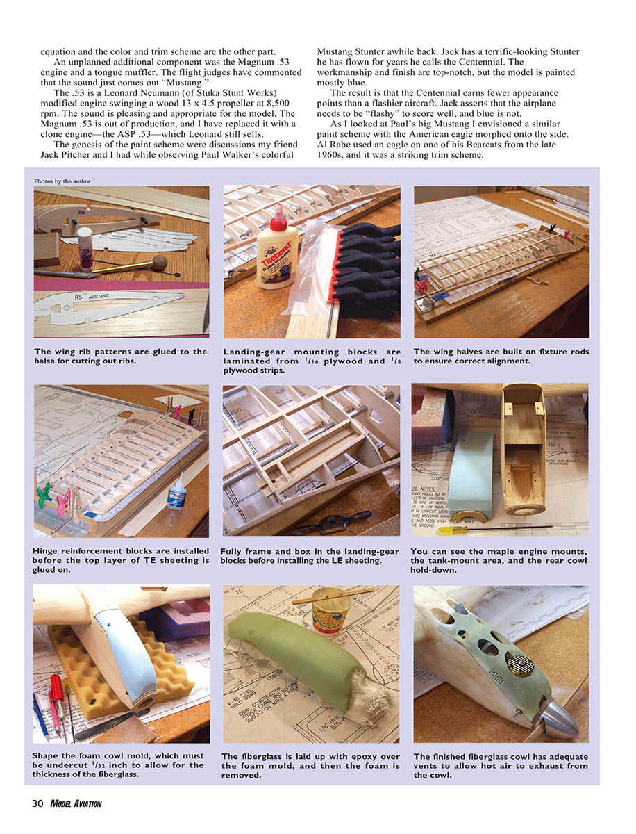
- Use cross-grain sheeting to add rigidity in high-stress areas like the nose and landing-gear mounts. Laminate the landing-gear blocks from 1/16- and 1/8-inch plywood before cutting them to final shape.
- The fuselage top is sheeted with 1/16-inch balsa over the formers and stringers. The stringers keep the sheeting from sagging between formers.
- The cowl is molded from foam and glassed with epoxy and 1-oz cloth. Shape the foam with a razor and spokeshave, undercutting the mold by 1/32 inch to allow for the fiberglass thickness. Remove the foam after the glass has cured.
- Install the firewall with maple motor mounts and add cowl hold-downs. Provide vents in the cowl to allow hot air to exhaust.
Spars and materials
- Pick higher-density balsa for the spars. Hard spars are cheap insurance for a strong wing. Carbon fiber could be applied to the spars, but I don't recommend it. Hard balsa is much less expensive and not nearly as hazardous with which to work.
- As does balsa, carbon fiber works great in tension. Balsa is five times stronger in tension than compression, and carbon fiber is even stronger under tension. However, both are much weaker under compression, which is the area we need to improve in the equation. Carbon fiber will buckle under compression unless supported with resins, and those cost weight.
- If you want to get fancy, you could make the spar from 1/4-inch balsa that is 3/8 inch wide at the root and tapers to 1/8 inch at the tip. That weighs the same as a 1/4-inch square spar but provides more strength toward the center of the wing, where it is needed. No matter what method is chosen, this wing is 2 1/2 inches thick, which makes it inherently strong anyway.
Ribs and assembly
- This design lends itself well to experimenting with different methods and materials. Feel free to do your own thing, but always think about how much a different part may weigh and what effect it will have on the CG.
- On my second Mustang I had a good supply of 5-pound stock, 3/32-inch balsa I used for the ribs. The weight difference was little, and after using this rib thickness I found it easier to work with than the customary 1/16-inch rib stock. You can choose whichever one you want to use.
- Stack the ribs on the fixture over a copy of the plans to align and space the ribs accurately. I use small draftsman's triangles to square everything up. Install the spars, the 1/8-inch LE, and the TE assemblies.
- The landing-gear mounts are shown built from 1/8- and 1/16-inch plywood supported with plywood rib doublers. I prefer this method to conventional hardwood landing-gear blocks, which are heavier. A 1/16-inch plywood gear cover laminated to a balsa block for shaping to the airfoil contour secures the 1/8-inch wire gear with 4-40 Allen-head screws.
Leading edge and shear webs
- As I mentioned in the overview, the wing LE is made from two layers of 1/8-inch balsa. The first layer holds the ribs in alignment and is trimmed to conform to the airfoil.
- The 1/16-inch LE sheeting is installed, and the front of the wing is block-sanded flat to receive the front piece of the 1/8-inch LE layer. This construction "locks" the sheeting into the LE and allows a nice radius to be sanded into the LE.
- Make sure the wing is still in the fixture when placing the vertical shear webs at the front of the TE and between the spars. The shear webs lock the wing into position and heavily resist twisting forces. The wing must be held straight in the fixture at this stage.
Dihedral, join, and controls
- Each wing-panel tip is raised 1 inch at the centerline of the root and tip ribs to establish the necessary dihedral. Join the wing halves and install the 4-inch bellcrank.
- I installed a flap-horn assembly I made from 3/32-inch music wire and brass stock. Don't worry about the dihedral. Just make sure the flap-horn wires are in line with the centerline of the flaps.
- The flaps will have hard-point horn boxes to receive the 3/32-inch-diameter wire horns. These allow enough lateral movement to permit free controls. I have experienced no problems using a one-piece control horn and dihedral. The center-section sheeting, capstrips, and wingtips complete the wing at this stage.
Leadout guide
- Install an adjustable leadout guide of your choice. I like the Paul Walker/Bill Werwage-type unit, which is 1/4-inch basswood with 1/8-inch-diameter holes drilled at 3/16-inch increments and a slot connecting all the holes. An eyelet may be pulled out, the leadout wire slid to the desired position, and then the eyelet pushed back in. This simple unit weighs roughly 4 grams.
Flaps and TE
- The flaps are solid 1/4-inch sheet stock, shaped to a taper. I also prefer to install a 1/4 x 1/4-inch plywood piece in the TE to establish a taper line, which also makes a hard TE that resists dents. A Dremel tool saw blade held in the Dremel router table is used to make a perfect slot for the plywood.
- As I mentioned, "lucky boxes" are installed in the flaps. These are plywood reinforcement boxes to accept the horn screws and provide a durable mounting surface.
Notes
- Make sure to install shear webs and fillets while the wing is in the fixture.
- Choose balsa densities and component methods with weight and compressive strength in mind.
- Vinyl masking for stars is an excellent time-saver for complex trim work.
Transcribed from original scans by AI. Minor OCR errors may remain.

