
SkyCruiser
By Clark Salisbury
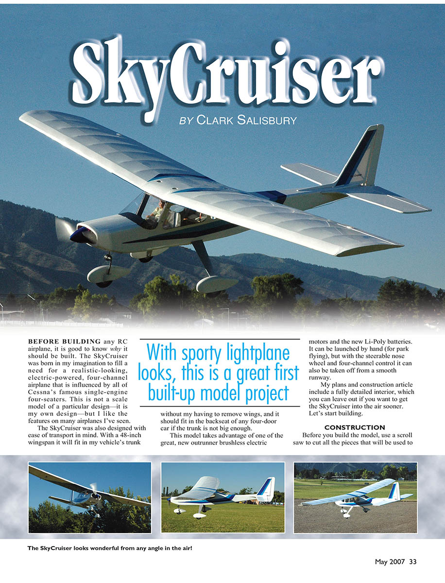
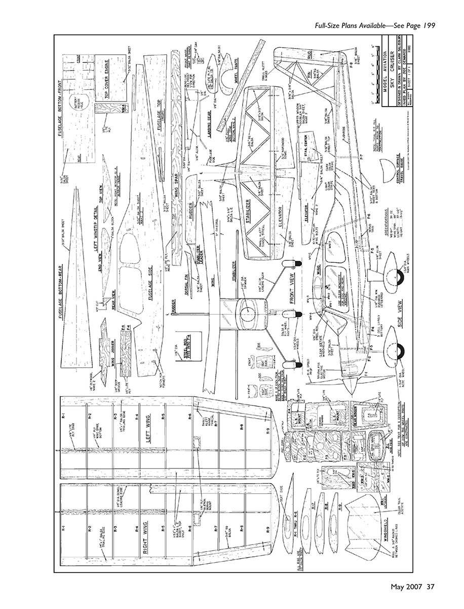
Before building any RC airplane, it is good to know why it should be built. The SkyCruiser was born in my imagination to fill a need for a realistic-looking, electric-powered, four-channel airplane that is influenced by Cessna’s famous single-engine four-seaters. This is not a scale model of a particular design—it is my own design—but I like the features on many airplanes I’ve seen.
The SkyCruiser was also designed with ease of transport in mind. With a 48-inch wingspan it will fit in my vehicle’s trunk without my having to remove wings, and it should fit in the backseat of any four-door car if the trunk is not big enough.
This model takes advantage of a new outrunner brushless electric motor and Li-Poly batteries. It can be launched by hand (for park flying), but with the steerable nose wheel and four-channel control it can also be taken off from a smooth runway.
My plans and construction article include a fully detailed interior, which you can leave out if you want to get the SkyCruiser into the air sooner. Let’s start building.
With sporty lightplane looks, this is a great first built-up model project.
CONSTRUCTION
Before you build the model, use a scroll saw to cut all the pieces that will be used to construct it. Adhere the plans to the wood with a glue stick, noting the grain direction, as shown on the plans. Stack pieces of wood for components that require more than one layer to build, as indicated on the plans. When doing so, use a tiny dab of glue on each corner to hold the stack together.
Wheel Pants
The wheel pants are the first items to construct. However, if your SkyCruiser will be flying off anything but a smooth runway, I don't recommend that you build them. They are mostly for looks and are fine if you can fly off a smooth runway with no big ruts or weeds.
For the wheel pants the plans call for 3/16" balsa stacked three high, with a layer of 1/16" balsa for the center-section of each. You can stack all those layers for three wheel pants and cut everything at the same time with a scroll saw since the total thickness will be 1 7/8".
You can stack the 1/16" pieces six high and cut them for the outside of all three wheel pants at the same time. Glue the outside pieces to the center-section and let the structure dry before sanding each wheel pant to its final shape.
The wheel pants need to be painted—not covered with MonoKote—and you should do this before assembly. Leave an unpainted place on the wheel pant for the retainer to be glued in later.
Seat Bases
The optional seat bases are made from 1" balsa block. Glue 3/16" balsa to both sides of the 1" block to make it thick enough for the seat bases and seat backs. It is easiest if you cut the radius contour and then cut out the side profile. Then cut out the top profile. After doing that, sand with fine sandpaper, glue the seat back to the seat pedestals, and then glue the seat base in place.
Tail Feathers
The tail feathers are easy to construct on a piece of drywall. T-pins stuck into the drywall will hold everything together while it's drying. Be sure to use a piece of waxed paper over the plans so the wood won't stick to them.
Hinges
Install the hinges at this point, slotting the balsa as shown on the plans. A cutoff wheel on a Dremel tool works well for making the slots. Do not epoxy the hinges yet.
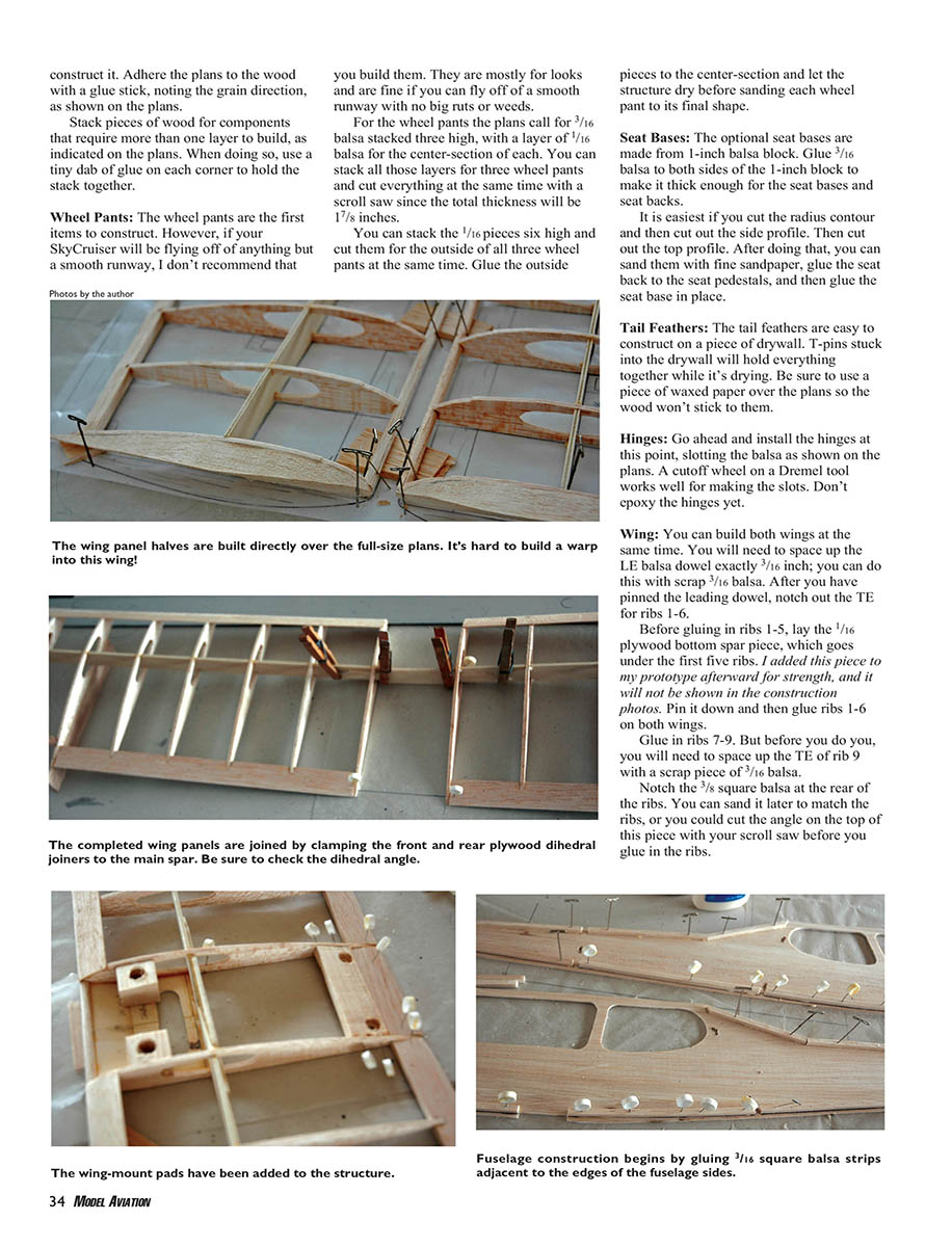
Wing
You can build both wings at the same time. You will need to space up the leading-edge (LE) balsa dowel exactly 3/16"; you can do this with scrap 3/16" balsa. After you have pinned the leading dowel, notch out the trailing edge (TE) for ribs 1–6.
Before gluing in ribs 1–5, lay the 1/16" plywood bottom spar piece, which goes under the first five ribs. I added this piece to my prototype afterward for strength, and it will not be shown in the construction photos. Pin it down and then glue ribs 1–6 on both wings.
Glue in ribs 7–9. Before you do, you will need to space up the TE of rib 9 with a scrap piece of 3/16" balsa.
Notch the 3/8" square balsa at the rear of the ribs. You can sand it later to match the ribs, or you could cut the angle on the top of this piece with your scroll saw before you glue in the ribs.
Glue in the wing spars. You can slide the spars through the holes in the ribs, then rotate the spar into position and glue all contact points.
Add the wingtips. Cut from a 1" balsa block using the pattern on the plans for the left wingtip. Cut a mirror image to make the right tip. The wingtips are cut lengthwise at a 45° angle. When gluing at the wingtips, the flat part of the tip should be facing up.
Add the 1/32" balsa sheet to the wing LE and hold with pins until the glue is dry. Add the ailerons. Fit the hinges, but do not glue them in place yet.
Remove the wing from the building board to make the hinge slots, and sand the entire wing before starting the next step. The LE and the wingtips will require the most sanding.
Install the front and rear dihedral joiners to maintain the 4.5° dihedral angle. Use the ailerons, which are exactly 1" wide, to hold the dihedral angle, under rib number 6 on both sides. Note that rib 1 to rib 1 is exactly 3 3/8", so draw two lines on your building board to hold this dimension.
Add wing mounts WM4, WM5, and WM6 between the R1 wing ribs. Install the 3 3/8"-long piece of trailing edge and a 3 3/8" piece of 1/4" diameter balsa dowel at the front of the wing.
Install four scrap pieces (made from 1" block) with 7/16" diameter holes above all four of the wing mounting holes. After this dries, sheet the top of the wing center with 1/32" balsa.
Ensure the wing has no twist or warp. A bit of washout is okay, but make sure you have the same amount on both sides and don’t exceed 1/4" when measured at the tips.
Fuselage
Begin fuselage construction by laying 3/16" square balsa along the outer edges of the fuselage sides (top and bottom). This is so the entire fuselage can be sanded to a 3/8" radius later and have enough material.
As you lay in these square balsa pieces, make sure they will be flush with the bottom of all of the formers (F1–F8). You will need to lay in the formers to determine where this is, and draw lines between the formers for locating the 3/16" balsa.
Glue in formers F2, F3, F4, and F6 to only one side of the fuselage. These formers should be perpendicular to the fuselage side pieces, and you will need something that holds them square.
Before you install former F4, mount the motor, cover it with a sandwich bag, and use an elastic to hold the bag on. The motor is practically impossible to mount later. The plastic bag protects the motor from paint when you spray the front of the fuselage later.
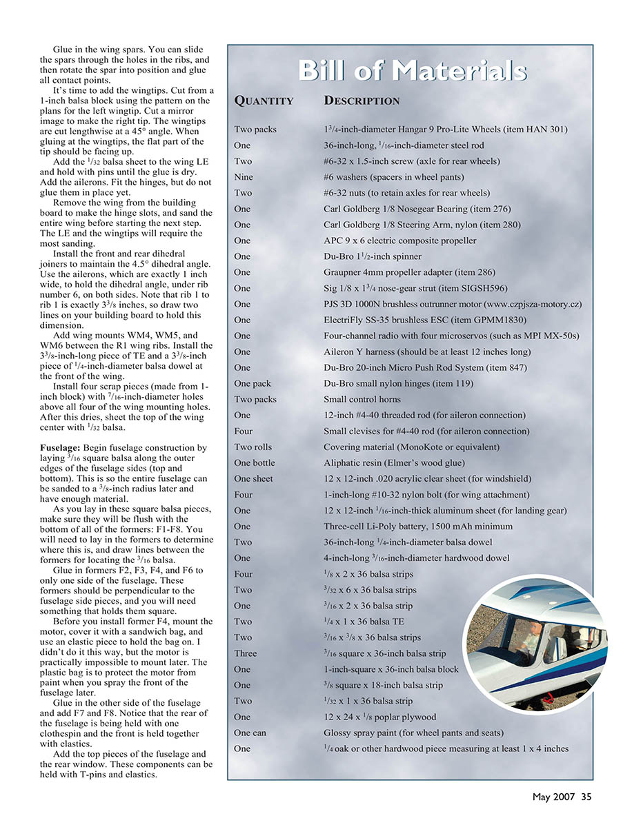
Glue in the other side of the fuselage and add F7 and F8. Notice that the rear of the fuselage is being held with one clothespin and the front is held together with elastics.
Add the top pieces of the fuselage and the rear window. These components can be held with T-pins and elastics.
The front cabin former (F4) is built as a separate assembly. The bent metal rod is epoxied into the grooves, and the assembly is held together with clothespins while it cures. This assembly includes WM1.
Although it’s not shown, glue in the wing mounts to the top of the cabin area—WM2 and WM3—along with the entire front former assembly you built earlier.
Install the nose-gear bearing on F3. Glue the F1 front nose piece in place and construct the optional removable front cover from scrap 1/4" balsa. This piece is unnecessary for flight, but it does improve the finished model’s realistic looks.
Glue in two 1/4" oak pieces and hold them in place with clothespins. These pieces are required only to attach the removable front cover. The front cover can be held in place with small wood screws going into the oak. This front cover is not detailed in the plans, but it will require sanding to match the front fuselage’s profile.
Install the rear under-fuselage balsa piece and hold it in place with pins to dry. Add the F5 former, which will support the servo tray. Make sure you install the servo tray at a height that will work with your servos and the mini pushrods going to the elevator and rudder.
Carefully sand the fuselage. This is perhaps the most important operation on the fuselage. Sand a 3/8" radius along the entire bottom of the fuselage and then along the top except where the wing will attach.
Install the main landing gear. The assembly of the landing gear with wheel pants is critical to make sure the wheels turn smoothly. The #6 screw goes through the aluminum formed gear and then into the wheel pant.
There is a #6 nut inside, then the wheel, then two washers on the other side of the wheel, which act as spacers. When this assembly is put together in this order, you can tighten the nut using curved needle-nose pliers. Drive the final small wood screw through the aluminum into the wheel pant to keep the wheel pant from rotating.
Assemble the front gear by using two washers as spacers on both sides of the wheel inside the wheel pant, and then glue the front wheel-pant retainer in place.
Install the front windshield and add the 3/8" radius by using your fingers to bend it. Using heat is unnecessary for this step; just roll the windshield with your fingers until the large radius is formed. Do not roll too hard or a tight radius will be formed instead. It is a good idea to practice on a scrap piece of acrylic before making the actual windshield.
SPECIFICATIONS
- Type: RC sport
- Wingspan: 48 inches
- Wing area: 403 square inches
- Flying weight: 34 ounces
- Wing loading: 12.1 ounces per square foot
- Power: PSJ 3D 1000N brushless outrunner motor (or equivalent), 35-amp ESC, 20C 1500 mAh 3S Li-Poly battery
- Construction: Balsa and light plywood
- Covering/finish: MonoKote or similar
Take your time and do a good job; this will make all the difference in the SkyCruiser’s finished appearance.
Covering and Painting
Cover the wing first, but make sure to install the Y-harness and the aileron servos before you cover the bottom of the wing. Make sure you cover the entire bottom of the wing, including the center-section; this will make it stronger.
If the wing is twisted, have a helper turn it back as necessary. While your aide is holding the wing, re-iron the MonoKote to remove the wrinkles caused by the warping.
Cover the tail pieces and then the fuselage. Use clear MonoKote for the side and rear windows, but don’t install the rear window until the rudder and elevator servos are hooked up to the pushrods; this window opening is handy for accessing those servos.
The color scheme is perhaps the most fun of the whole project. You can personalize the airplane with the colors you use or employ the one that I dreamed up.
Equipment Installation
Install the radio receiver, the servos, the speed controller, and then the battery, which can be placed in the bottom of the fuselage or partly on top of F4. Attach the radio receiver and battery with nylon ties through the bottom of the fuselage to get the CG correct, as shown on the plans.
Drill a 2" diameter hole in the bottom of the fuselage to allow the battery to be charged and for the connection from the ESC to the battery when you are ready to fly. You may want to add scrap balsa pieces around the 2" hole for reinforcement.
If the brushless motor turns backward when you hook the three wires to the ESC, exchange the connections on any two of the wires and the motor will rotate correctly.
(Editor’s note: It is highly recommended that you make the battery removable for charging for safety’s sake.)
FLYING
A prototype taking to the air for the first time is a nervous occasion, and I am glad I had my friend and accomplished test pilot Dave Stuart make the first flight for me. I was taking video of the entire first flight, so I had a good excuse not to make it!
Dave was surprised by how quickly the SkyCruiser lifted off from the runway at full throttle (in approximately 20 feet). Once airborne, he trimmed a couple of clicks nose-up and then tried a few maneuvers.
Elevator travel was excessive, so Dave put the radio on low rate and proceeded to do loops and aileron rolls. The model does not roll very quickly, but it wasn’t designed for quick rolls. He also performed a stall-spin routine, during which the SkyCruiser went flat in a bit of altitude. Dave’s comment was that the model likes best to fly around at half throttle, doing gentle maneuvers.
It was also clear that the airplane can do some aerobatic maneuvers, but this is not an aerobatic aircraft and the design purpose was met. Dave commented on the model’s tendency to gain altitude at full throttle instead of just speed.
I made an angle-of-incidence adjustment on the prototype by removing the horizontal stabilizer and changing the angle of incidence. This improved the flight performance. I also readjusted the elevator travel. The model plans reflect both changes.
Many happy flights. MA
Clark Salisbury 671 E. 2160 N. North Logan, UT 84341
Transcribed from original scans by AI. Minor OCR errors may remain.

