

Trimming From the Ground Up Part 3
by Dean Pappas
In the previous installment of this “Trimming From the Ground Up” series I wrote about improving the ground handling during takeoff and improving the controllability of the model in the critical seconds after liftoff. Right-thrust and downthrust adjustments figured prominently.
In this installment I will approach the largest subject: directional controllability. I saved the best for last!
In the original list of airplane personality problems presented in Part 1, the first two items were devoted to directional control problems. As with the pitch discussion we started with two months ago, there is a balance of trim forces in roll as well as in yaw. Let’s address the roll forces.
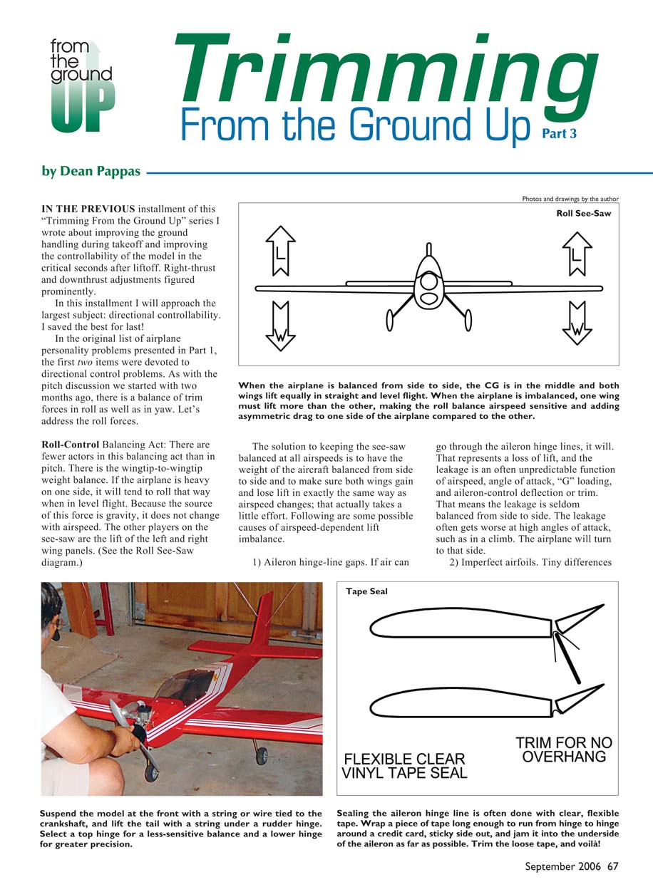
Roll-Control Balancing Act There are fewer actors in this balancing act than in pitch. There is the wingtip-to-wingtip weight balance. If the airplane is heavy on one side, it will tend to roll that way when in level flight. Because the source of this force is gravity, it does not change with airspeed. The other players on the see-saw are the lift of the left and right wing panels. (See the Roll See-Saw diagram.)
When the airplane is balanced from side to side, the CG is in the middle and both wings lift equally in straight and level flight. When the airplane is imbalanced, one wing must lift more than the other, making the roll balance airspeed sensitive and adding asymmetric drag to one side of the airplane compared to the other.
The solution to keeping the see-saw balanced at all airspeeds is to have the weight of the aircraft balanced from side to side and to make sure both wings gain and lose lift in exactly the same way as airspeed changes; that actually takes a little effort. Following are some possible causes of airspeed-dependent lift imbalance.
- Aileron hinge-line gaps. If air can go through the aileron hinge lines, it will. That represents a loss of lift, and the leakage is an often unpredictable function of airspeed, angle of attack, “G” loading, and aileron-control deflection or trim. That means the leakage is seldom balanced from side to side. The leakage often gets worse at high angles of attack, such as in a climb. The airplane will turn to that side.
- Imperfect airfoils. Tiny differences in airfoil shape from side to side (especially the rounding of the leading edges) can require that the ailerons be trimmed to counteract. The aileron deflection and airfoil shape will have different airspeed characteristics, so the trim will be upset as the airspeed changes.
- Wing warps, even subtle ones, will require the ailerons to be trimmed to counteract, and these two also vary with airspeed. The warp usually maintains its influence at very low airspeeds better than the aileron deflection.
- If the ailerons are trimmed to one side to counteract a problem caused by the rudder trim not being centered (or a crooked fin!), the balance between these control surfaces is upset as airspeed changes.
Back Into the Workshop!
There are a few things we need to do before we leave the workshop to make life easier at the field. As we did in the section on pitch, we will fiddle around in the shop for a bit. However, almost all of this could be done at the field if you don't mind wasting daylight on a flying afternoon.
Let's cover side-to-side balancing. First let's balance those wings. It is surprising how far off-balance many airplanes are. The muffler alone can do that; many weigh close to a half pound and may sit 4 or 5 inches from the center of the airplane. If there are one or two heavier sheets of wood in one wing panel than in the other, the resulting imbalance can be severe.
When that happens, you have a difference in the required lift from one wing to the other. At high speed this imbalance can easily be counteracted with a tiny bit of aileron trim. That's usually how we set the transmitter trims in our airplanes: in cruise-speed level flight.
For some of us, cruise speed is at full throttle. No problem; I like to go fast too! At landing speed the imbalanced wing weight doesn't change, but the aileron and rudder effectiveness do, so the model starts to wander off to the heavy wing.
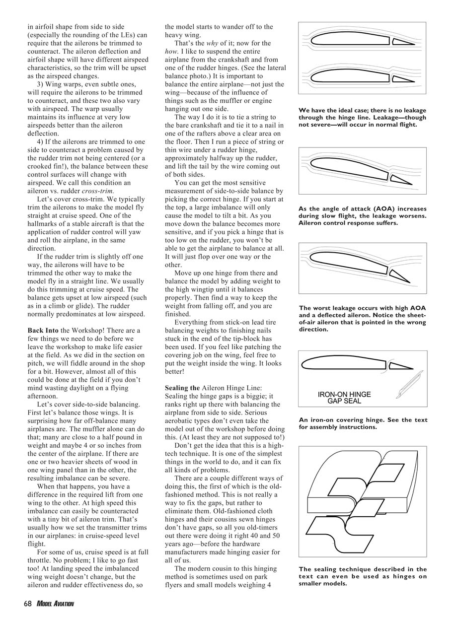
That's the why of it; now for the how. I like to suspend the entire airplane from the crankshaft and from one of the rudder hinges. (See the lateral balance photo.) It is important to balance the entire airplane—not just the wing—because of the influence of things such as the muffler or engine hanging out on one side.
The way I do it is to tie a string to the bare crankshaft and tie it to a nail in one of the rafters above a clear area on the floor. Then I run a piece of string or thin wire under a rudder hinge, approximately halfway up the rudder, and lift the tail by the wire coming out of both sides.
You can get the most sensitive measurement of side-to-side balance by picking the correct hinge. If you start at the top, a large imbalance will only cause the model to tilt a bit. As you move down the balance becomes more sensitive, and if you pick a hinge that is too low on the rudder, you won't be able to get the airplane to balance at all. It will just flop over one way or the other.
Move up one hinge from there and balance the model by adding weight to the high wingtip until it balances properly. Then find a way to keep the weight from falling off, and you are finished.
- Everything from stick-on lead tire-balancing weights to finishing nails stuck in the end of the tip block has been used. If you feel like patching the covering job on the wing, feel free to put the weight inside the wing. It looks better!
Sealing the Aileron Hinge Line
Sealing the hinge gaps is a biggie; it ranks right up there with balancing the airplane from side to side. Serious aerobatic types don't even take the model out of the workshop before doing this. (At least they are not supposed to!)
Don't get the idea that this is a high-tech technique. It is one of the simplest things in the world to do, and it can fix all kinds of problems.
There are a couple different ways of doing this, the first of which is the old-fashioned method. This is not really a way to fix the gaps, but rather to eliminate them. Old-fashioned cloth hinges and their cousins sewn hinges don't have gaps, so all you old-timers out there were doing it right 40 and 50 years ago—before the hardware manufacturers made hinging easier for all of us.
The modern cousin to this hinging method is sometimes used on park flyers and small models weighing 4 ounces and up. For models of 2 pounds and less, this technique can be done with tape or iron-on covering.
Short lengths of covering are ironed together, sticky side to sticky side, with roughly 1/8 or 1/4 inch of overlap. The pieces are ironed to the top and bottom of the fixed surface, in an alternating fashion, and each piece is fed through the hinge gap in an "S."
After a little work with an iron, you have a gap-free hinge. It's light, simple, and economical. I don't recommend this for larger models. (See the Iron-On "S" Hinge drawing.)
Many of us use an iron-on plastic covering for at least the wings and tail feathers. Even with trim schemes that cut across the hinge lines or color changes from fixed to moving surfaces, we can do a pretty job with the same covering material.
To make a seal that does not tighten and sag when the controls are moved, we have to make an "S" seal as with the hinges above. You can even use different colors in each half of the "S" bend to match the colors on the top and bottom of the airplane.
The beauty of the "S" seal is that it does not tighten and bind the control surface—even at 3-D control throws. Clear iron-on covering can also be used if there are too many color changes near the hinge line.
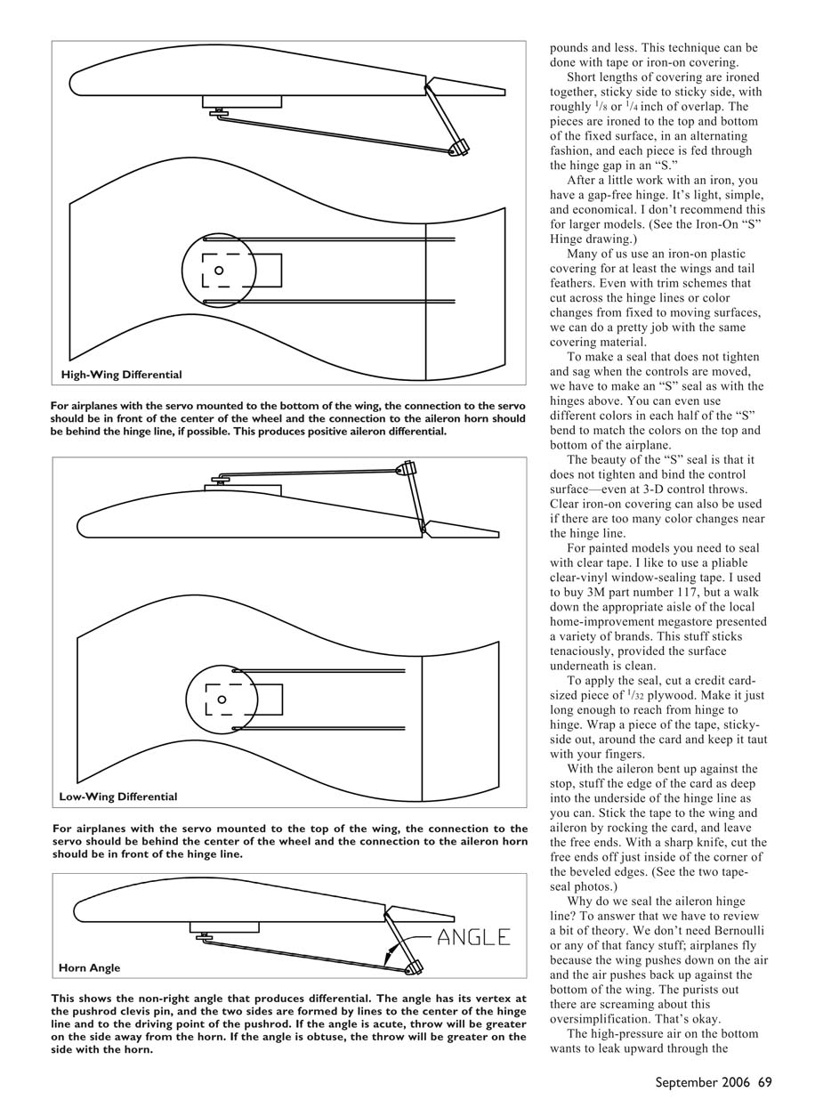
For painted models you need to seal with clear tape. I like to use a pliable clear-vinyl window-sealing tape. I used to buy 3M part number 117, but a walk down the appropriate aisle of the local home-improvement megastore presented a variety of brands. This stuff sticks tenaciously, provided the surface underneath is clean.
To apply the seal, cut a credit card–sized piece of 1/32 plywood. Make it just long enough to reach from hinge to hinge. Wrap a piece of the tape, sticky-side out, around the card and keep it taut with your fingers.
With the aileron bent up against the stop, stuff the edge of the card as deep into the underside of the hinge line as you can. Stick the tape to the wing and aileron by rocking the card, and leave the free ends. With a sharp knife, cut the free ends off just inside of the corner of the beveled edges. (See the two tape-seal photos.)
Why do we seal the aileron hinge line? To answer that we have to review a bit of theory. We don't need Bernoulli or any of that fancy stuff; airplanes fly because the wing pushes down on the air and the air pushes back up against the bottom of the wing. The high-pressure air on the bottom wants to leak upward through the aileron hinge gap.
The effect of high-pressure air leaking out from under the wing, through the gap between the wing and aileron, is bad. Sometimes it is really bad. (See the hinge-line leak drawing.) This leakage causes a loss of lift and hampers good roll control.
An old friend I lost track of many years ago had a Piper J-2 Cub. You could stick your fingers and palm right through the aileron hinge-line gaps.
The J-2 was slower than molasses in January and had pitiful aileron response during a stall. At airspeeds only a few mph faster than stall speed, the ailerons worked backward! If overused they could force the airplane to drop into an unwanted spin entry. That's the way the Cub was designed!
Pilots who trained on this airplane decades ago were taught to use rudder as the primary roll control during near-stall conditions. In those days spin training was necessary just to get a private pilot's license.
Back to the Cub. Yellow duct-tape seals on the ailerons (they had to be yellow, didn't they?) improved the cruise speed by a whole 4 mph, and the ailerons worked all the way through the stall. That is abnormal for any Cub! It also briefly put the airplane in the experimental category.
Aileron seals have no bad effects that I am aware of. They can actually have good effects such as saving servo power, preventing flutter, and making the airplane behave better during takeoff and landing.
The problem of aileron hinge-line leakage gets worse when the airspeed is low and the angle of attack is high, and it gets even worse when aileron is drooped. High angles of attack result from pulling Gs or from flying slowly. As the angle of attack increases, the leak worsens.
The leak is further worsened when you apply aileron control. Picture the left wing as you roll into a right turn. The depressed aileron forces the air downward so that the local air pressure is even greater. The leaking air squirts out as a "sheet" that eventually breaks up and joins the airflow past the wing.
Until it breaks up, that sheet of air looks like an aileron pointed the wrong way. It's not made from wood, but it is real.
Let's put this together. Your model is climbing steeply just after takeoff, and you push right aileron to start a turn. The left aileron goes down and the right one goes up. The sheet of air leaking on the left wing gets worse, and you have an airplane with the right aileron going—well, the wooden aileron goes down, but the aileron made from a sheet of air goes up at the same time.
As a result, the left wing has a big drag brake on it. That doesn't help when turning right!
This yaw in the opposite direction of the desired roll is called adverse yaw, and it's bad. Sealing the gaps gets rid of the leakage problem and reduces (but not eliminates) adverse yaw. It also makes the ailerons more powerful, so you can reduce the aileron throw and still get the same control effectiveness.
Time to Go Flying Again
In trimming for good directional control we have two main goals:
- Trim the (now sealed) ailerons and rudder so that the model is not crosstrimmed and flies straight at all speeds from slow to fast.
- Achieve predictable aileron response at all speeds—especially slow. The two critical flight regimes are the steep climb right after takeoff and the critical low-speed turns used to line up with the runway for landing and to counteract wind on final approach.
Aileron and Rudder Trim
This topic overlaps the right-thrust adjustment discussion. There was no straightforward way to get a handle on both subjects at one time, but we will combine the tests and adjustments at the field.
When an airplane is crosstrimmed it behaves differently turning left vs. turning right. Let's say the model has the rudder offset to the right. The ailerons will have to be trimmed left in cruise flight to fly a straight line. In fact, the aircraft will be crabbing to the right in straight flight. The same sort of thing happens when a car has the rear axle bolted in crooked.
When this airplane is turned to the left it will tend to hang its nose "out of the turn" and may even constantly tend to roll back to level flight. When turned to the right, this model will tend to "wind into the turn" and even try to roll over into a spiral dive.
You already know the test to detect a crosstrim: make left and right turns, always using the same bank angle, and adjust the rudder trim away from the direction of turn that winds in. Every time you adjust the rudder, go back to trimming the ailerons for straight and level flight. As are many other trimming adjustments, it's an iterative process and you'll have to go back and forth a few times to get it right.
When you think you have it right, try a long glide at idle power as a fine-adjustment test. Set up with the airplane flying straight into the wind, and repeat the hands-off glide test a few times if there is any kind of wind out. If the model wanders off to one side, tweak the rudder trim to correct and retrim the ailerons again.
Any difference between this test and the turn test is generally caused by subtle wing warps or other assembly issues. You'll have to accept any difference that remains between left and right turns, although nine out of 10 times the glide and turn tests agree.
Your aircraft is now really trimmed to fly straight. Landings can be prettier, and more effort can be put into that picture-perfect three-point flare rather than fighting to keep the model from veering off the runway.
Rock and Roll—Making the Ailerons Work Well at All Speeds
Do you remember the anecdote about the L-19 Bird Dog from Part 2 of this series? That airplane had a bad adverse-yaw problem, as do many high- and shoulder-wing models with high-lift airfoils.
During the takeoff climb that turned left over the pits and spectators, the pilot had gobs of right aileron control cranked in but the airplane kept wandering off to the left. A lack of right thrust might have been partly to blame, but the aileron control should have worked well enough to turn the airplane right. It didn't, and the reason was severe adverse yaw with aileron application.
There's another scenario. You throttle back and initiate the turn to your final approach for landing. As the model lines up with the runway, you apply opposite aileron to level off and stop the turn, but the nose keeps cranking around for just a heartbeat longer and the ailerons don't work immediately.
There is a time lag, and when the airplane finally responds it wallows as it rolls. That's right; it's adverse yaw. We have already sealed the aileron hinge lines, but...
Adverse Yaw Is Fundamental
Adverse yaw is not just a problem caused by aileron hinge gaps; even with perfect gaps there will be adverse yaw. Again, the problem gets worse at low speed and at high angles of attack. Now we need to look at what is called "aileron differential."
Let's say you want your airplane to roll right to exit a left turn. The right aileron is raised and the left one is lowered. The desired result will be to lift the left wing and lower the right.
Lifting is work—especially when you're lifting furniture. Wingtips aren't that heavy, but they do count. So we are asking the left wing to do more work and the right wing to do less work. The energy needed to do this work comes from the creation of drag.
The force of drag multiplied by the distance through which it is applied equals work. This means the wingtip being raised has more drag than the wing being lowered. That drag imbalance tries to yaw the model the wrong way compared to the desired roll.
How do we fix this? After all, its cause is buried in the physics and energetics of flight. It's not a workshop problem such as hinge gaps.
Three Ways to Skin This Cat—Piloting Technique
There are three things we can do:
- Use coordinated aileron and rudder, the technique full-scale pilots use. Apply rudder with aileron to counteract adverse yaw. In some aircraft, rudder is applied slightly before aileron. This skill is worth developing for RC pilots, but it may be too much to expect from beginners.
- Couple the ailerons into the rudder electronically or mechanically so that applying aileron also applies some rudder (aileron-into-rudder coupling). Many modern radios support this, or aftermarket mixers are available. Typically full aileron might require roughly one-quarter rudder or less; you'll need to test and fine-tune the coupling.
- Use aileron differential. This is the preferred method for most flyers. The aileron that goes up must travel farther, in degrees, than the one that goes down. This can be done mechanically via link geometry or electronically with a programmable radio using independent servos for each aileron. A good differential setting often works for most of the flight envelope, though some coordinated rudder may still be needed in the steepest climbs.
Dutch Roll Aileron Differential Test (Also For Coupled Aileron Into Rudder)
Fly a straight line away from yourself at a safe but low altitude. Smoothly but quickly rock the aileron stick back and forth so the airplane banks 45° one way and then the other way.
You want to use as much aileron throw as you can while comfortably keeping up with the airplane. Ideally the rhythm will be approximately a half second in one direction and the same back in the other direction. One of three things will happen:
- Axial Rolling. The airplane will roll back and forth, and the tail will point straight at you and not wiggle at all. The airplane will appear to roll on a fixed axis, as if it were riding on a wire. That means the differential is perfect for level flight.
- Adverse Yaw. The model "duck walks": as the airplane rolls right, the tail wiggles right; as it rolls left, the tail wiggles left. That means the nose is going in the direction opposite the roll—and that's the wrong way. You need more differential or more aileron-into-rudder coupling.
- Proverse Yaw. The nose wiggles the same way as the bank. You don't see this often. It can look like the beginning of a sudden turn. This is acceptable for trainers and can help initiate turns, but if you want to remove it reduce the differential or reduce the aileron-into-rudder coupling.
Let's Retest in a Climb
Adverse yaw is worst at low airspeeds, such as in a climb. Repeat the Dutch roll test in a climb, pointed directly away from you, using the steepest climb angle you normally expect to use.
The trick to this test is being able to sight down the tail of the airplane. The corrective actions are the same as the level-flight Dutch roll test.
Heavy, slow, or short-tailed scale airplanes will benefit tremendously from optimizing their differential for the takeoff climbout. The climbing differential test will often uncover an adverse-yaw problem that requires a lot of differential. It may be too much to practically put into your control linkages. If so, consider one of several approaches:
- Learn to move the rudder stick in unison with the ailerons.
- Use coupled aileron-into-rudder (CAR).
- Install two separate aileron servos to get more differential adjustment (if your radio is programmable and supports an aileron differential menu).
Don't be surprised if some airplanes need twice as much throw on the rising aileron as on the dropping one.
Feeling Cranky—How to Mechanically Adjust Aileron Differential
The differential crank is an ancient mechanical device; that means it is deceptively simple and sophisticated at the same time. The methods described work with one servo driving both ailerons or with a separate servo for each aileron. If you have a radio that allows you to electronically adjust the differential and use separate aileron servos in each wing, you might skip the next couple paragraphs.
If your airplane has the servo(s) and control horns on the bottom of the wing, the proper differential happens if the aileron horns are behind the hinge line and/or the connections to the servo wheel are in front of the center of the wheel. This is typically the situation on a high-wing airplane or a two-servo low-winger. (See the High-Wing Differential drawing.)
If your airplane has the servo(s) and control horns on top of the wing, the aileron horns need to be angled forward and/or the connections to the servo wheel need to be behind the center of the wheel. This is usually the situation on a single-servo low-winger. It's that simple. A careful look at the drawings should help untangle the whole mess. (See the Low-Wing Differential drawing.)
Since it requires a bit of shop time, we want to leave the workshop with the differential set to a good guess for starters. Your typical low-wing sport model is usually happy when the rising aileron goes up approximately 20% more than the other goes down (all amounts are for throw angles, in degrees).
A high-wing trainer would like approximately two-to-one, but the mechanical method shown in the diagram will only get you close. My recommendation for trainers, especially the ones with flat-bottom airfoils, is to connect to the servo wheel roughly 30° in front of the hold-down screw and to rake the aileron horns back so that the angle of the control horn is 90°.
Let me define the control-horn angle clearly. If you draw a line from the middle of the hinge line through the little hole that the clevis pin goes through, it makes an angle with the clevis pin at the vertex with the pushrod. If you are using a bent-wire strip aileron horn, this is easier when you use a fitting that does not move the clevis pin forward of the heavy wire horn. The plastic part that is often included in the kit moves the clevis pin more than 1/4 inch forward of the bent-wire horn.
Nelson Hobby/Rocket City and Sonic-Tronics make an ideal piece of hardware. These products place the clevis pin directly in the middle of the music-wire aileron horn.
The recommendation for how much differential to put into a trainer may seem to be a lot, but a full-scale Cessna 150 has one-and-a-half-to-one differential; the upmoving aileron moves 15° while the other one drops 10°.
Even so, in cruise flight the aileron response still requires coordinated rudder to make the airplane respond properly. On takeoff and in landing trim it definitely needs aileron-rudder coordination. You wouldn’t expect a high-wing model to be much different from a Cessna 150, now would you?
Remember that if a stable trainer-type model has inadequate differential, the aileron response will have an initial lag, after which the control effectiveness will still be sluggish. Control lags lead to overcontrol and stick thrashing—good for churning butter, but not for flying.
Tidying Up
This concludes my collection of trim techniques for training and Sunday flying. I hope I have given you not just a cookbook method for trimming, but a good start in understanding the whys and hows of trimming an airplane.
As it turns out, there is a whole body of advanced trimming techniques for sport, aerobatics, and 3-D flight regimes. We have a reason to get back together.
MA
Dean Pappas [email protected]
Transcribed from original scans by AI. Minor OCR errors may remain.

